


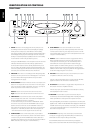
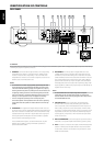
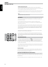

7 DIGITAL INPUTS, OPTICAL & COAXIAL : Connect to the coaxial/
optical S/PDIF-format digital output of sources such as VCRs, HDTV,
satellite tuners or other components. Connect OPTICAL/COAXIAL
DIGITAL INPUT to an S/PDIF-format digital output. We recommend your
source material be set to PCM 2-channel format for these digital inputs.
8 DIGITAL OUTPUT, OPTICAL : Connect the OPTICAL DIGITAL
OUTPUT port to the corresponding S/PDIF digital input of a recording
component such as a CD recorder, DAT deck or computer soundcard.
9 COMPONENT VIDEO OUT : Connect the L 54’s “COMPONENT VIDEO
OUT” to the component video input of a compatible video monitor/TV.
Be sure to observe consistency in connecting the appropriate Y, Cb/Pb,
Cr/Pr jacks to the corresponding sources/inputs. Do not rely purely
on the color coding of the jacks, which may not always be consistent
among brands. The routing of the component video output is xed.
The L 54’s component-video output is a fully wide-band output,
compatible with all HDTV formats. On-screen display menu is also
shown at component video output.
NOTES
• Make sure to set ‘VIDEO OUT’ to ‘COMPONENT’ at the SETUP menu for
video to be available at Component Video OUT. See also section VIDEO
OUT” at “Setup Menu” discussion.
• “COMPONENT VIDEO OUT” jack will only display the internal DVD
video signals.
10 AC POWER CORD : Connect AC power cord to the voltage according
to the model, 120V for US and 230V for Euro models.
The clock resets to “00:00” when the AC power cord is unplugged and
then plug-in again to the power source.
11 SWITCHED AC OUTLET : This convenience jack can supply switched
power to another component or accessory. It is powered on and o by the
front panel POWER button (or the HTR 4’s ON and OFF buttons).The total
draw of all devices connected to this jack must not exceed 100 watts.
12 SCART/RGB OUT (Euro model/PAL only) : Connect the L 54’s
“SCART/RGB OUT” to the SCART/RGB video input of a compatible video
monitor/TV. Be sure to observe the correct orientation of the SCART/
RGB plug. Make sure also to set ‘VIDEO OUT’ to ‘RGB’ at the SETUP menu
for stable video availability at SCART/RGB OUT.
13 MONITOR OUT : Connect to video input of the monitor/television,
using quality RCA and/or S-Video cables designed for video signals. In
general, the S-Video connection is superior and should be used if your
TV/monitor provides the corresponding input.
Make sure also to set ‘VIDEO OUT’ to ‘S-Video’ at the SETUP menu for
video to be available at ‘S-Video’ Monitor OUT.
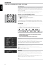
IDENTIFICATION OF CONTROLS
REAR PANEL
ENGLISHFRANÇAISDEUTSCHNEDERLANDSESPAÑOLITALIANOРУССКИЙSVENSKA
11