14
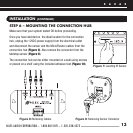
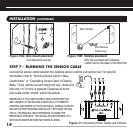
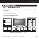
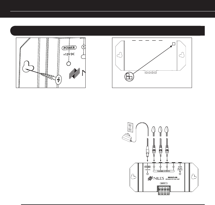
Figure 10B: Tabletop placement
Affix the enclosed self-adhesive
Figure 10A:
Wall-mount placement
Self-Adhesive
Rubber Feet
INSTALLATION (continued)
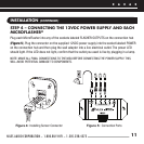
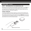
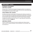
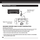
Figure 11: Connecting Power Supply and Flashers
STEP 7 – RUNNING THE SENSOR CABLE
Conceal the sensor cable between the tabletop sensor and the connection hub. For specific
information refer to “Running Sensor Cable in New
Construction” or “Concealing Sensor Cable in Existing
Walls.” If you need to cut and restrip the wire, make sure
that only 1/4” of wire is exposed. Exposing too much
wire could create “shorts” within the system.


