


User’s Manual
13
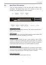
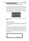
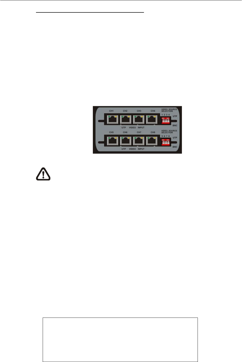
UTP Input (for 4ch & 8ch models only)
Short for Unshielded Twisted Pair, which is a popular type of cable. Due to its
low cost, UTP cabling here is used for replacing BNC cabling.
There are plenty of UTP connectors positioned on the rear panel of each unit.
Next to these connectors places a switch used to enable or disable this
function. Each switch (4ch DVR only has one switch and 4ch/ 8ch DVR has
two) has four DIP switches on it. These DIP switches are named by numbers;
and each number corresponds to a camera. Note that BNC are alternative
methods of access for video input cabling, which means if you chose BNC for
Camera 1, than you have to disable its UTP function.
NOTE: UTP cable transfers not only Video Signal but also power for
cameras.
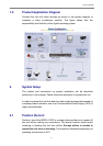
3. General System Setup
The MPEG-4 DVR allows user to access some general operations through
the front panel easily. The following subsections introduce the general
operations of the unit.
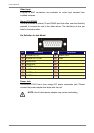
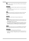
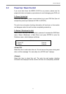
The regular displayed OSD information and its displayed positions are shown
as following figure. The channel title will be displayed on the top-left side of
the window, either in full screen mode or in multiple channel mode. The
current operating mode, including Call mode, Dome-Control mode, Playback
mode. Freeze mode and Sequence mode, will be displayed on the
bottom-left side of the screen. And the date/ time information will be display
on the bottom-right side.
Ch4
Playback
2005/11/09 PM04:31:22