


Identification of Controls
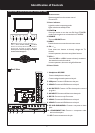
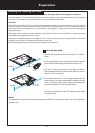
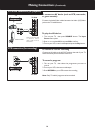
Main Unit (Front View/Bottom View/Back View)
7
1. Remote sensor
2. Power indicator
Lights blue when in operating mode.
Lights red when in standby mode.
3. POWER
4. SOURCE
To access SOURCE menu
5. MENU
Press this button to access the main menu screen.
6. CH
Press these two buttons to directly change the TV
channel;
In menu operations, also serve as up/down buttons.
7. VOL+
Press the VOL+ or VOL– button to directly increase or
decrease the sound volume level;
In menu operations, also serve as right/left buttons.
8. Power Switch
Receives signals from the remote control.
Do not block.
Press this button to turn the unit ON from STANDBY
mode. Press it again to turn the set back to STANDBY.
^
/
^
/–
Note: B
^
uttons on the TV control panel (CH / ,
^
VOL+/-, MENU, SOURCE, POWER ) are touch
buttons. First touch of the button will illuminate it.
Second touch will fulfill its function. Be sure
button presses must be quickly done before
the illumination disappears.
SOURCEMENU
CH VOL
1 2
SOURCE
MENU
CH VOL
+
3 4 5 6 7
Front View/Bottom View
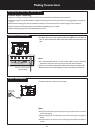
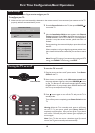
Back View
8
1. Headphone & S/PDIF:
Connect headphones to this jack.
Connect a digital sound system to this jack.
2. USB port: Connect a USB device to this port.
3. HDMI3: Connect an HDMI device to this jack.
4. AV OUTPUT: Connect a VCR to these jacks to record
programs.
5. AV INPUT: Connect an AV device to these jacks.
6. RS-232: For service only. Do not use.
7. HDMI1: Connect an HDMI device to this jack.
8. HDMI2: Connect an HDMI device to this jack.
9. PC IN D-SUB/AUDIO: Connect a computer to these
jacks.
10. COMPONENT IN: Connect a component video
device to these jacks.
11. RF: Connect an antenna to this jack.
HDMI 3
AV IN
VIDEO
AUDIOL R
USB
AV OUT
VIDEO
S/PDIF
AUDIOL R
1
2
3
4
5
6
7 8 9 11
AUDIO
D-Sub
PB
PR
Y L R
COMPONENT IN
AUDIO
RS-232
HDMI 1 HDMI 2
PC IN RF
10