


10
PUSH PUSH
PUSH PUSH
REMOTE
ON
1
2
IN
SIGNAL
GND
DC IN
OUT
OFF
AUDIO OUT
LR
MONITOR
(SUPER)
75≠
HD/SD REF VIDEO IN
VIDEO OUT
SD SDI
OUT
DC OUT
12V 250mA
TC
AC IN
FUSE 125V 2.5A F1
CH
2
CH
1
CH
1
CH
4
CH
3
CH
2
CH
3
CH
4
AUDIO IN
IN
OUT2
OUT1
HD SDI
1
>5=>
24
3
?
6
87; :<
9
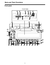
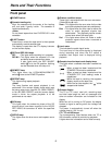
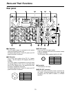
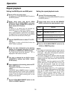
Rear panel
Parts and Their Functions
1AC IN socket
The AC power supply is connected to this socket
using the accessory power cord.
AC power takes priority if both AC power and DC
power have been connected.
2DC IN socket
This is the input socket of the DC 12 V power
supply. Use the optional AC adapter (AJ-B75 or
AJ-B95).
The VTR’s power is automatically turned off when
the voltage drops to 10.6 V or so. It may take some
time for the voltage level to be restored even after
the supply voltage has recovered.
AC power takes priority if both AC power and DC
power have been connected.
3DC OUT socket
This is the DC 12 V output socket.
Power is supplied from here to the external remote
controller (AJ-A95).
The DC power cable is packed with the AJ-A95.
4Fuse holder
This houses a 2.5 A fuse.
5SD SDI OUT connector
This is the down-conversion output connector for
the digital component audio and video signals
complying with the SMPTE 259M-C or 272M-A
standard.
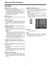
Pin No. Signal
1 Ground
2 ———
3 ———
4 +12 V
1
2
3
4
3
1
2
4
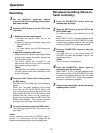
Pin No. Signal
1 Ground
2 ———
3 ———
4 +12 V