12
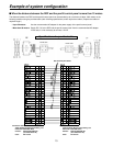
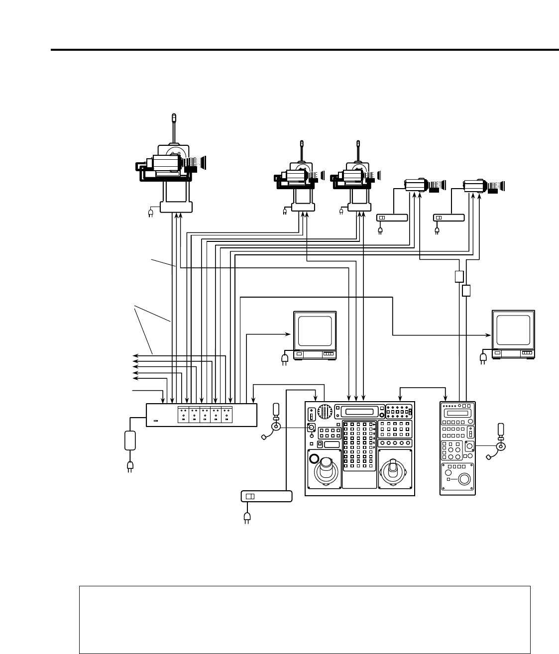
Example of system configuration
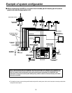
$ When connecting the ROP in a system that includes pan/tilt heads, pan/tilt control
panel and cable compensation unit
Convertible camera
Pan/Tilt Head
AW-PH400
Composite video or
component video
signals
To switcher,
monitor
G/L
AC adaptor
AW-PS505
Cable provided
with AW-CB400
AW-CA50T8
or
AW-CA50T9 +
RS-422/RS-232C
converter
Monitor
Headset
Headset
Monitor
Monitor switching
Genlock signals
MONITOR2
MONITOR1
Remote
Operation Panel
AW-CB400
Pan/tilt Control Panel
AW-RP400
Cable Compensation
Unit
AW-RC400
When a pan/tilt head system and cameras have been connected to the CONTROL OUT connectors on
the pan/tilt control panel and the CONTROL OUT connectors with the corresponding numbers on the
ROP, the camera control exercised by the pan/tilt head system connected to the CONTROL OUT
connectors on the pan/tilt control panel takes priority, and the camera connected directly to the ROP
cannot be controlled.
❈ For details on how to connect the pan/tilt heads and pan/tilt control panel, refer to the instruction manual provided with
the pan/tilt control panel.
Cable provided
with AC adaptor
AC adaptor
AW-PS301


