4
Accessories
Introduction
Contents
This remote operation panel (ROP) enables up to five
convertible cameras to be controlled.
Menu items can be selected on the ROP’s LCD display to
set the functions of the cameras.
The connection distance between the ROP and convertible
cameras can be extended up to a maximum of 1000 meters.
By connecting the ROP to the pan/tilt control panel using the
cable supplied, the convertible cameras mounted on the
pan/tilt heads can be controlled.
This Operating Instruction describes each apparatus as
follows;
Pan/tilt control panel: AW-RP400
Pan/tilt head: AW-PH400
Cable compensation unit: AW-RC400
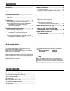
Introduction ............................................................. 4
Accessories ............................................................. 4
Precautions for use ................................................. 5
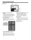
Parts and their functions ........................................ 6
Front panel ..................................................................... 6
Rear panel ...................................................................... 9
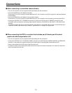
Connections .......................................................... 10
When connecting a convertible camera directly ........... 10
When connecting the ROP in a system that includes
pan/tilt heads, pan/tilt control panel and
cable compensation unit ......................................... 10
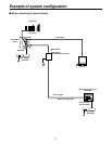
Example of system configuration ........................ 11
When connecting a camera directly ............................. 11
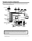
When connecting the ROP in a system that includes
pan/tilt heads, pan/tilt control panel and
cable compensation unit ......................................... 12
When the distance between the ROP and the pan/tilt
control panel is more than 10 meters ...................... 13
Operating procedure ............................................. 14
Turning on the power ................................................... 14
Adjusting the cable compensation of each camera....... 14
Genlock adjustments for each camera ......................... 14
Video adjustment of cameras ....................................... 15
Menu settings ........................................................ 16
Operation method ......................................................... 16
Items which can be selected on
the camera setting display ..................................... 17
Items which can be selected on
the remote operation panel setting display ............ 19
How to mount the ROP in a rack ......................... 20
Joining the ROP to the AW-RP400 and
mounting the joined-up units in a rack ........... 20
How to change the position of
the connector panel
.......................................... 21
Specifications ........................................................ 22
Pan/tilt control panel (AW-RP400) connecting cable ...... 1
Tally/INCOM connector (D-SUB 15-pin) ......................... 1
Rack-mounting adaptors ................................................. 2
Join-up fixture .................................................................. 1
Mounting screws (M4!8 mm) ........................................ 8
Join-up screws (stepped screws) .................................... 2
Joining sticker .................................................................. 2
Note
When the remote operation panel is to be discarded at
the end of its service life, ask a specialized contractor to
dispose of it properly in order to protect the environment.


