


- 12 -
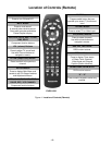
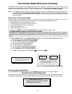
Chassis Service Adjustment Procedures
All service adjustments are factory preset and should not require adjustment unless controls and/or
associated components are replaced.
Note: Connect the (-) lead of the voltmeter to the appropriate ground. Use heat sink when the HOT ground symbol
( ) is used. Otherwise, use COLD ground ( ) — Tuner shield.
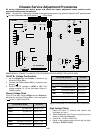
MOMENTARILY CONNECT A JUMPER FOR ENTERING SERVICE MODE (TP8 to COLD GND)
140.0V B+ Voltage Confirmation
1. Set the Bright and the Picture to Minimum by
using the Picture Menu.
2. Connect the DVM between
TPP17
(+ side) and cold
ground ( ).
3. Confirm that B+ voltage is 140.0V ± 1.5V. This
voltage supplies B+ to the Horizontal Output &
Flyback circuits.
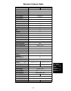
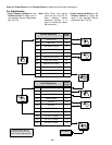
Source Voltage Chart
120V AC line input. Set the Bright and the Picture to
Minimum by using the Picture Menu. Use cold ground
(
) for the (-) lead of the DVM.
.
Adjust Picture Menu for normalized video adjustments.
High Voltage Check
1. Select an active TV channel and confirm that
horizontal is in sync.
2. Adjust Brightness and Picture using Picture Icon
menu so video just disappears.
3. Confirm B+ 140.0V is within limit.
4. Using a high voltage meter confirm that the High
Voltage is 31.0kV ± 1.0kV.
T
U
N
E
R
TP
18
A/V REAR INPUTS
IC101
D-BOARD
A-BOARD
T
U
N
E
R
IC002
IC882
IC2301
D825
D751
T801
L826
Q551
Q801
L824
D827
Q804
C840
-
+
D511
IC1801
IC001
IC881
IC3001
IC883
L008
Q002
C3023
-
+
LOCATION (D-Board) VOLTAGE
TPP17
(by D825)
+B2 140.0V ± 1.5V
TPP25
(by D827)
9V 9.0V ± 1.5V
TPP19
(by Q804)
15V 15.0V ± 2.0V
TPP20
(by C840)
15V (VER.) 15.0V ± 1.5V
TPP21
(by L826)
-15V (VER.) -15.0V ± 1.5V
TPP22 (
by L824
) SOUND 32.5V ± 2.0V
TPD7
(by D511)
220V 220.0V ± 9.0V
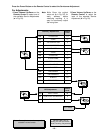
LOCATION (A-Board) VOLTAGE
TPA6
(by IC883)
MAIN 12V 12.0V ± 0.5V
TPA7
(by IC3001)
MAIN 9V 9.0V ± 0.5V
TPA8
(by L008)
MAIN 5V 5.0V ± 0.3V
TPA16
(by Q002)
STBY 3.3V 3.3V ± 0.2V
TPA18
(by C3023)
BTL 30V 32.0V ± 2.0V
LOCATION (D-Board) VOLTAGE