


- 30 -
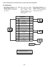
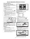
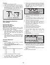
V-Correction Adjustment (D02)
Preparation:
1. Apply a Crosshatch pattern.
2. Adjust (D01) so that V-Size is regular size.
3. If b-a<-1.5mm (in top and bottom), increase (D02)
by one step and adjust (D01) so that V-Size is
regular; repeat steps until b-a
≤
1.5mm
4. If b-a>-1.5mm (in top and bottom), decrease (D02)
by one step and adjust (D01) so that V-Size is
regular; repeat steps until b-a
≤
1.5mm.
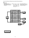
MTS Circuit Adjustments
The MTS Circuit Adjustments require two steps:
1. Input Level Adjustment.
2. Stereo Separation Adjustment.
Input Level Adjustment (M00)
Preparation:
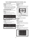
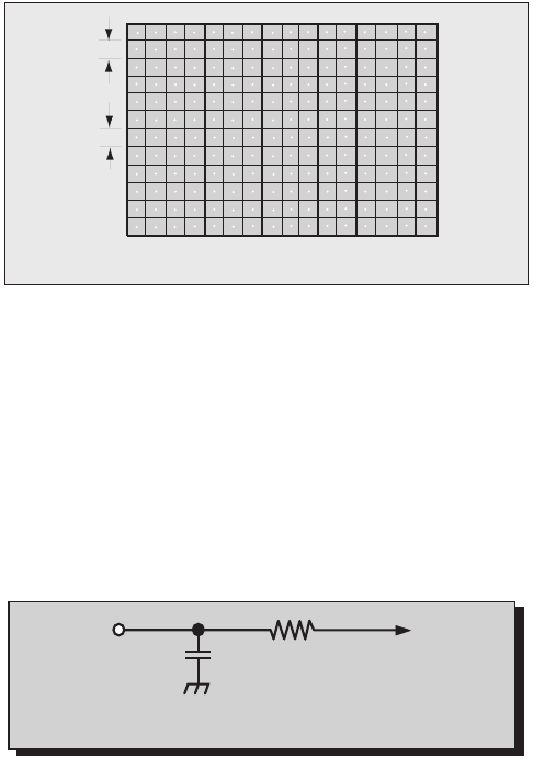
1. Connect an RMS meter with filter jig as shown in
Fig. 37.
2. Connect an RF signal generator to the RF
antenna input.
Procedure:
1. Apply the following signal from the RF signal
generator:
Video: 100 IRE flat field, 30% modulation.
Audio: 300Hz, 100% modulation, monaural
(70 ±5dB, 75Ω OPEN, P/S 10dB).
2. Adjust the MTS Input Level Adjustment (M0) until
the voltage measured is 106 ± 6.0mV rms.
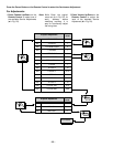
Stereo Separation Adjustment
(M01 & M02)
Preparation:
1. Connect an RF signal generator to the RF antenna
input.
2. Connect oscilloscope to TPE10.
Procedure:
1. Select Stereo Mode in Audio menu
2. Apply the following signal from the RF signal
generator:
Video: 100 IRE flat field, 30% modulation.
Audio: 300Hz, 100% modulation, stereo (left only)
(70 ±5dB, 75Ω OPEN, P/S 10dB).
3. Adjust the MTS Low-Level Separation Adjustment
(M01) until the amplitude displayed on the scope
is minimum.
4. Apply the following signal from the RF
signal generator:
Video: 100 IRE flat field, 30% modulation.
Audio: 3KHz, 100% modulation, stereo (left only)
(70 ±5dB, 75Ω OPEN, P/S 10dB).
5. Adjust the MTS High-Level Separation Adjustment
(M02) until the amplitude displayed on the scope is
minimum.
6. Repeat above steps 2 through 5 until the amplitude
is minimum for both signals.
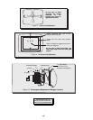
a
b
Figure 36. V-Adjustment
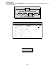
10k
4700p
TPE11
RMS
METER
Figure 37. Filter Jig