


- 5 -
Service Notes (Continued)
IMPORTANT: To protect against possible damage to
the solid state devices due to arcing or static
discharge, make certain that all ground wires and CTR
DAG wire are securely connected.
CAUTION: The power supply circuit is above earth
ground and the chassis cannot be polarized. Use an
isolation transformer when servicing the Receiver to
avoid damage to the test equipment or to the chassis.
Connect the test equipment to the proper ground () or
( ) when servicing, or incorrect voltages will be
measured.
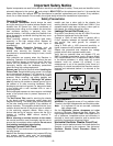
WARNING: This Receiver has been designed to meet
or exceed applicable safety and X-ray radiation
protection as specified by government agencies and
independent testing laboratories.
To maintain original product safety design standards
relative to X-ray radiation and shock and fire hazard,
parts indicated with the symbol on the schematic
must be replaced with identical parts. Order parts from
the manufacturer’s parts center using the parts
numbers shown in this service manual, or provide the
chassis number and the part reference number.
For optimum performance and reliability, all other parts
should be replaced with components of
identical specification.
Horizontal Oscillator Disable Circuit
This chassis employs a special circuit to protect
against excessive high voltage and beam current. If, for
any reason, the high voltage and beam current exceed
a predetermined level this protective circuit activates
and detunes the horizontal oscillator that limits the high
voltage. The over-voltage protection circuit is not
adjustable. However, if components indicated by the
symbol on the schematic in either the horizontal
sweep system or the over-voltage protection circuit
itself are changed, the operation of the circuit should
be checked using the following procedure:
Equipment needed to check the disabled circuit:
1. DC Ammeter
2. High Voltage Meter (0- 50kV electrostatic)
3. Variac or Isolation Transformer
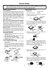
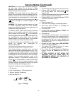
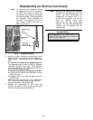
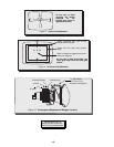
4. HHS Jig (See Fig. 2)
Figure 2. HHS Jig
Preparation
1. Connect Receiver to AC 120 Volts. Do not turn ON.
2. Connect HIGH VOLTAGE meter to 2nd anode
(H.V. button).
Note
:
Use cold ground( ) for
negative lead.
3. Connect the ammeter serial from the flyback anode
lead to the picture tube anode socket.
4. Prepare HHS jig to be connected between TPD50
and TPD51 as shown in Fig. 2.
Procedure
:
1. Open Connector A17.
2. Turn power ON and Apply a monoscope pattern.
3. Set current within 50-100µΑ
by changing the
picture and bright controls.
4. Turn power OFF.
5. Connect HHS jig between TPD50 and TPD51 (VR
should be turn fully clockwise).
6. Turn power on.
7. Turn slowly the variable resistor to increase the
current until the horizontal sync frequency abruptly
increases indicating that the horizontal frequency is
just beginning to pull out of sync. Maintain the
current within
50-100µΑ
by changing the picture
and bright controls
8. Observe the High Voltage meter. HIGH VOLTAGE
should read less than 40.2kV.
9. Turn power OFF, Remove HHS jig, HV meter,
ammeter and connect A17 connector.
10. Turn Power ON. Reset Picture and Brightness
controls. Confirm B+ 140V±1.5V with 120V AC
applied.
11.
IF HIGH VOLTAGE IS NOT WITHIN THE
SPECIFIED LIMIT THE CAUSE MUST BE
DETERMINED BEFORE THE RECEIVER IS
RETURNED TO THE OWNER.
TPD50
TPD51
100Ω
1KΩ