


- 9 -
Disassembly for Service
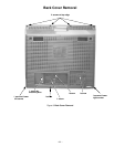
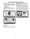
Back Cover
Remove all the screws marked with an arrow( )
from the back of the Receiver.
Note: Screw configuration, type, and number
of screws vary depending on the
model of the Receiver serviced and
the application; various models are
covered in this Manual. Use same
hardware when reassembling the
receiver.
• 4 screws at the top edge of the Receiver.
• 4 screw by the A/V jacks.
• 1 screw by the antenna jacks.
• 1 screw at each lower corner of the Receiver.
• 1 screw by the retainer plate of the AC power cord.
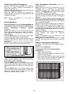
A-Board - Main Chassis
The A-Board assembly rest on a chassis tray along
with the D-Board. Slide chassis tray out. Gently lift tray
and pull out. Disconnect plug connectors; release wire
ties and holders as required for complete chassis
removal.
1. A & D-Boards are secured to the chassis tray with
five screws.
2. The A-Board is mated to the D-Board by three
flexible connectors: A1, A2 & A3 (G1, G2 & G3 on
the G-Board, respectively). To remove either
boards, unplug the connectors on the A-Board.
Note: Some tie-wraps that secure the wire dressings
may need to be unfastened for chassis
removal.
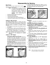
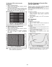
L-Board - CRT Output
Plugs into the socket on the CRT neck.
To remove this board, first unplug the board from
the CRT neck, then disconnect L1, L2 & L3
connectors, to disconnect the focus F1(Red Cable)
& F2(White Cable) cables, pull the tab and release
the cables, finally disconnect the screen cable from
the D-Board Fly-Back.
To reinsert back the cables, remember the original
position of cables, F1(red cable) goes to A on the
CRT socket and F2(white cable) goes to B on the
CRT socket.
Figure 5. F1 & F2 cables release
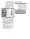
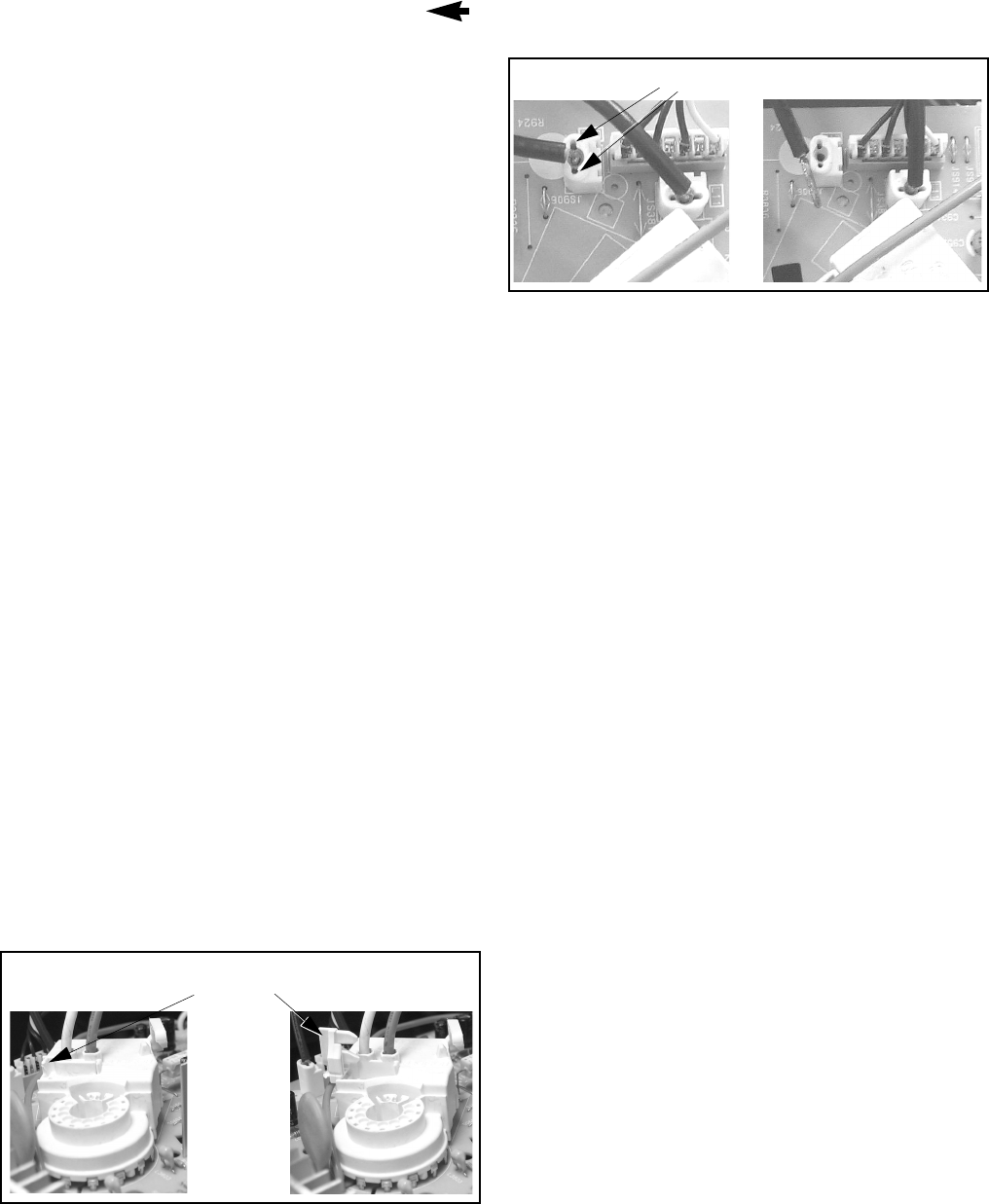
To release screen GND cables from L-Board L11 & L12
connectors, insert a wire in both sides of connector and
pull upwards the cable, then remove the wire
(See Fig. 6)
Figure 6. L-Board Screen GND cables release
Speakers
Speaker is secured to the cabinet’s front with 4
screws.
Keyboard Push Button Assembly
Fastened to the inside of the cabinet front.
Disassembly for CRT Replacement
1. Discharge the CRT as instructed in the Safety
Precautions (see page 2).
2. Disconnect the yoke (DY) plug, degaussing coil
(DEG) plug and the CRT 2nd anode button from
the board.
3. Remove the L-Board from the CRT socket and
unplug the black wires (CRT dag ground) L11 &
L12.
4. Lift the Main Chassis (A-Board) and all mounted
boards completely out with the CRT Board attached.
CRT Replacement
1. Perform Disassembly for CRT Replacement
procedure.
2. Insure that the CRT H.V. Anode button is
discharged before handling the CRT. Read the
Safety Precautions (see page 2) on handling the
picture tube.
3. Remove the components from the CRT neck and
place the cabinet face down on a soft pad.
4. Note the original order for the CRT mounting
hardware as they are remove from the CRT
mounting brackets at each corner of the CRT.
5. Remove the CRT with the degaussing coil and the
dag ground braid attached.
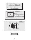
Press tab
release cables
leftward to
Pull cables
upwards
Pull cable upwards
Insert wire
Note:
After servicing the receiver, remember
to dress the cables, as shown above.