


26
English
CY-TUN153U
27
English
CY-TUN153U
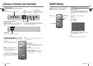
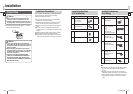
Electrical Connections
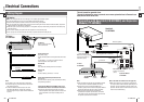
Wiring Diagram
25 26
Power Control Lead
(Blue/white stripe)
To the external amplifi er control power lead of the Head
Unit.
To ACC power, 12 V DC, if the Head Unit has no
external amplifi er control power lead.
Battery Lead
(Yellow)
To the car battery, continuous 12 V DC.
Ground Lead
(Black)
To a clean, bare metallic part of the car chassis.
Parking Brake (Side Brake) Connection Lead
(Bright green)
Be sure to wire the parking brake (side brake) for safety
and preventing accidents.
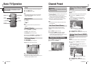
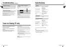
TV Tuner:
CY-TUN153U
Power connector
Caution
This unit is designed for use in a car having a 12 V negative ground battery system.
To prevent damage to the unit, be sure to follow the connection diagram.
Do not insert the power connector into the unit until the wiring is completed.
Be sure to insulate any exposed wires to prevent short circuiting with the car chassis. Bundle all cables, and prevent
cable terminals from touching any metal parts.
Note that if your car has a driving computer or a navigation computer, disconnecting the cable from the battery may
clear the memory.
Run the cords avoiding the spots where the temperature can be extremely high.
Fit a vinyl cap over unused connection terminals, to prevent contact with metal parts etc.
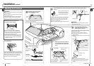
Note:
Strip about 5 mm of the lead ends for connection.
Be sure to fully plug in the connectors. Secure them
with clamps and tapes.
All other installation methods require the use of
dedicated metal fi ttings. Consult with a qualifi ed
servicing engineer or your dealer if other methods are
required.
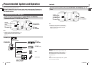
Note:
Refer to individual instruction and installation manuals
for each device for detailed installation and wiring.
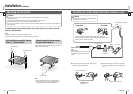
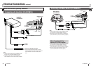
Connect this unit to the Expansion Module (CY-
EM100U, option) with the Head Unit/Expansion Module
Connecting Cable and RCA cord (video) (supplied).
When the device that provides video output is
connected to the System-up Connector, connect the
video cable to input connector below the port to which
the System-up Connector is connected.
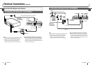
Connecting with Head Unit (CQ-VD7003U) and Expansion
Module (CY-EM100U)
This unit cannot be operated alone.
This unit is designed for users to connect one or more system devices to Panasonic car
audio/AV unit at the same time.
Note for the Head Unit remote control unit (page 13):
With some Head Units, the Head Unit remote control
unit may not have buttons intended specifi cally for TV
operation, so some operations cannot be used for TV
operation. But that does not mean that the tuner or the
Head Unit are malfunctioning.
(Fuse 3 A)
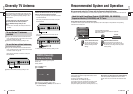
TV Antenna
Refer to page 24 for the TV
antenna connection.
REMOTE IN
Not used.
Head Unit:
CQ-VD7003U
Expansion Module:
CY-EM100U
TV Tuner:
CY-TUN153U
VIDEO
(Yellow)
TO EXPANSION
MODULE
RCA cord
Head Unit/Expansion
Module Connecting Cable
To one of the system-up
connectors (input)
Head Unit/Expansion Module Connecting
Cable (supplied with CY-EM100U)
Port 1 IN to 4 IN
System-up connectors
(input)
Video input
Video input
RCA cord (option)
Video (Yellow)
Video
(Yellow)
If the Expansion Module (CY-EM100U, option) is not
connected and the ACC is not mounted on the vehicle:
Connect the power control lead of this unit to the
external amplifi er control power lead of the Head Unit.
If this connection is not made, the battery will run
down.
Not used.