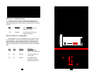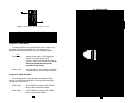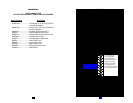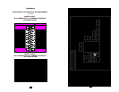
Jumper JP1: Power Source
The Model 2070/Dx may be powered by the X.21 interface or by
the supplied AC wall-mount transformer. The setting for JP1
determines how the Model 2070/Dx receives its operating power.
JP1
Position 1&2 Interface Power Option. In this setting the
2070/Dx is powered from the DTE
interface. Power should be applied to DB-15
pin 15 at +5VDC (±5%), 300mA (min) The AC
wall-mount transformer must not be
connected in this setting.
Position 1&3 AC Power Option. In this setting, the 2070/Dx
is powered by the AC wall mount transformer
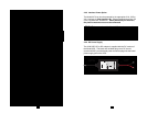
Jumper JP2: SGND & FRGND
In the default position, Signal Ground is connected to Frame
Ground. In the disconnected position, this strap disconnects Signal
Ground and Frame Ground.
Position 4&6 G.703 FRGND connected to DTE FRGND.
Both are disconnected from SGND
.
Position 5&6 G.703 FRGND connected to DTE FRGND
Both are connected to SGND
17
2070/Dx JP1 AND JP2 SUMMARY TABLE
Position Function Factory Default
JP1 Power Source 1&3 AC Powered
JP2 SGND to FGND 5&6 Connected
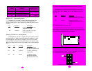
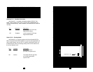
Figure 14. Possible Settings of Jumper Straps JP1 and JP2
1
2
3 4
5
6
JP2
JP1
4.0 INSTALLATION
The Model 2070 is designed for 4-wire, full duplex communication
over a co-directional 64 kbps G.703 clear channel network or dedicated
twisted pair. This section describes the proper connection of the line
interface, the DTE (terminal) interface, and AC/DC power.
4.1 CONNECTING TO A PCM NETWORK CHANNEL
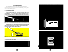
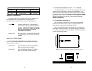
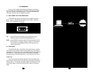
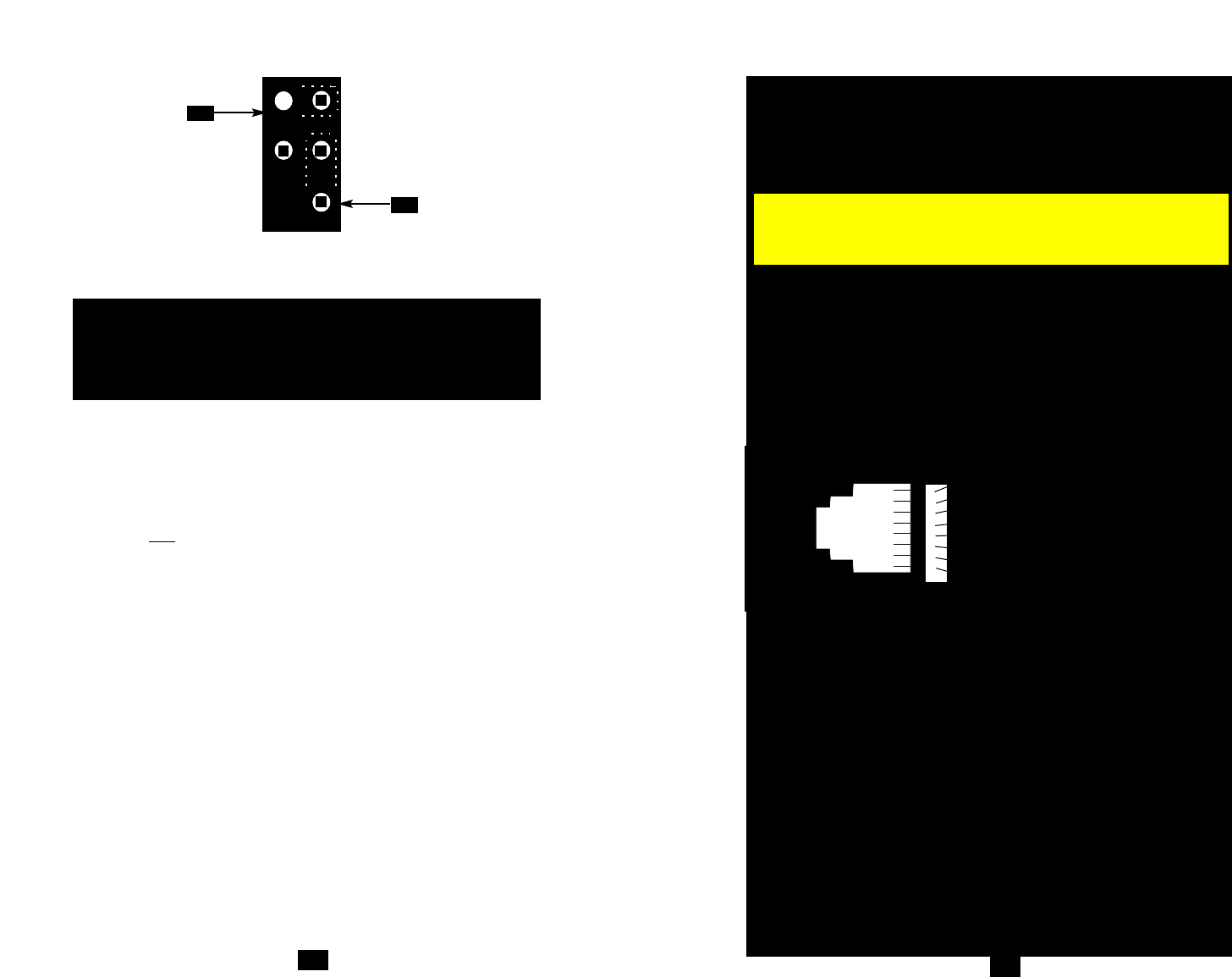
The RJ-45 port on a Model 2070 is pre-wired for direct connection
to the G.703 PCM network. Connect the RJ-45 port of the Model 2070
to the RJ-45 jack provided by your digital service carrier using a
straight through twisted pair cable between 19 and 26 AWG. To be
sure you have the right wiring, use the diagram below as a guide.
4.2 CONNECTING OVER PRIVATE TWISTED PAIR
If you wish to connect the Model 2070 to another Model 2070 (or
compatible G.703 device) over private twisted pair, make the
connection between the two devices using a crossover cable pinned
according to the diagram below.
RJ-45 Cable (8-W
ire)
SIGNAL PIN# PIN# SIGNAL
RX+ 1-----------------------5 TX+
RX- 2-----------------------4 TX-
TX+ 5-----------------------1 RX+
TX- 4-----------------------2 RX
Shield 3-----------------------3 Shield
Shield 6-----------------------6 Shield
18
1 (RX+)
2 (RX-)
3 (N/C)
4 (TX-)
5 (TX+)
6 (N/C)
7 (N/C)
8 (N/C)
1
2
3
4
5
6
7
8
Notice! The G.703 line surge protection on this unit was
installed for circuit protection only. By no means does this
include the preservation of signal quality during a large surge.


