


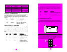
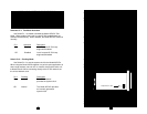


Switches S1-1: Test Mode Activation
Use Switch S1-1 to enable or disable the Model 2070/Cx Test
Mode. When enabled, the Local Line and G.703 loopback tests are
activated simultaneously. When disabled, the Model 2070/Cx functions
normally.
S1-1
Activation Description
On Enabled Local Loop and G.703 Loop
diagnostics enabled
Off Disabled Local Loop and G.703 Loop
diagnostics disabled
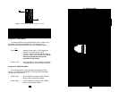
Switches S1-2 and S1-3: Clocking Mode
Use Switches S1-2 and S1-3 together to set the system clock for
the Model 2070/Cx. When using two Model 2070s together in a point-
to-point application as short range modems, set one unit for either
Internal or External transmit clock and the other unit to Network clock.
When connecting directly to the G.703 network, set the unit to Network
clock.
S1-2 S1-3 Clocking Description
On On Network The G.703 network
provides the system clock
On Off External The DTE provides the
system clock
Off On Internal The Model 2070/Cx
provides an internally
generated system clock
11
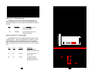
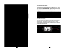
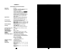
MODEL 2070/Cx SWITCH S1 SUMMARY TABLE
Position Function Factory Default
S1-1 Test Mode Off Disabled
S1-2 Clock Mode On
S1-3 Clock Mode On
S1-4 Response to LL Request On Disabled
}
Network
Clock
Switch S1-4: Response to DTE Request for Local Loopback
Use Switch S1-4 to enable the Model 2070/Cx to enter Local
Loopback mode when pin L from the V.35 interface is raised. In the On
position, the Local Loopback may only be enabled manually by Switch
S1-1.
S1-4 Activation Description
On Disabled Model 2070/Cx ignores requests
to enter Local Loopback
Off Enabled Model 2070/Cx enters Local
Loopback Mode when pin 18 is
raised
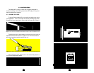
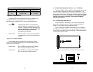
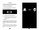
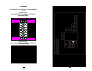
3.3.2 Jumper Straps “JP1” and “JP2”
The Model 2070/Cx uses two jumper straps (JP1 and JP2, see
Figure 9 below) to select the power source option and to connect the
unit signal ground to frame ground.
Figure 10 shows possible settings of jumper straps JP1 and JP2.
JP1 may be positioned on pegs 1 and 2 or on pegs 1 and 3. JP2 may
be positioned on pegs 4 and 6 or on pegs 5 and 6.
12
Figure 9. Location of Jumpers JP1 and JP2 on the top of the Model 2070/Cx PC board
Figure 10. Possible Settings of Jumper Straps JP1 and JP2
1
2
3 4
5
6
JP2
JP1
1
3
5
2
4
6
Jumpers JP1
& JP2