5.0 OPERATION
Once you have configured the Model 2070 properly (see Section
3.0) and made line, DTE and power connections correctly (see Section
4.0), you are ready to operate the unit(s). This section describes the
LED status monitors, and the loopback test mode.
5.1 BACK PANEL LED STATUS MONITORS
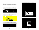
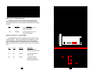
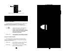
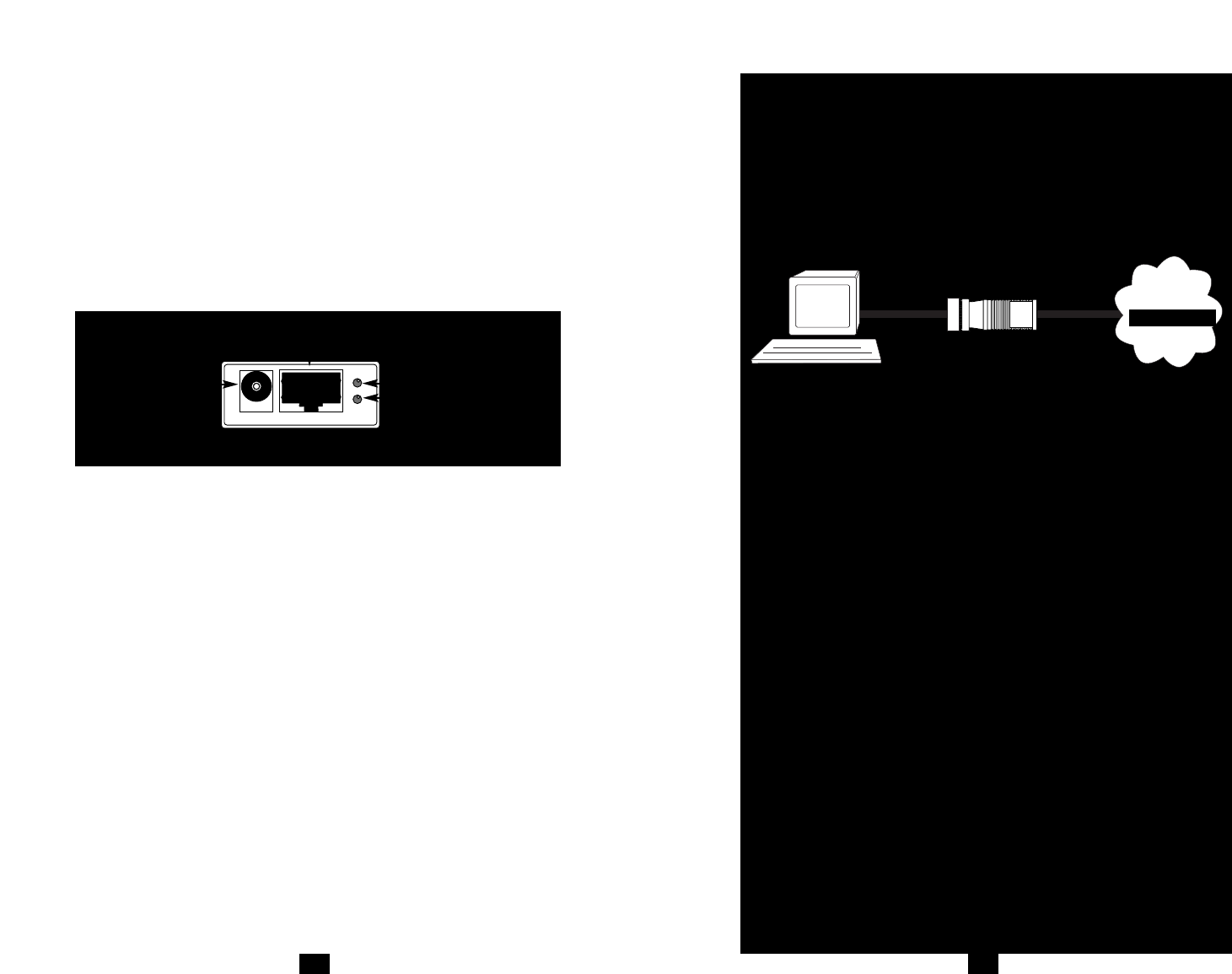
The Model 2070 features two LEDs that are located on the back
panel. Figure 11 below shows the positions of the LEDs. Following
Figure 15 is a description of each LED.
TM glows RED when Test Mode (Local Loop/G.703 Loop) is
initiated manually or by the DTE (See Section 3.0).
SYNC glows GREEN to indicate a valid G.703 synchronization to the
terminal device. No signal indicates no data, no connection or
synchronous clock slippage on either the G.703 side or the
terminal device side.
5.2 TEST MODE
The Model 2070 offers a Test Mode that may be used to evaluate
the condition of the modems and the communication link. Test Mode is
composed of two diagnostics that are activated simultaneously either by
DIP Switch S1-1 or by a signal on the terminal interface. This section
describes the two Test Mode diagnostics: Local Loop and G.703 Loop.
Local Loop
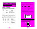
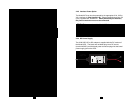
The Local Loop test checks the operation of the local 2070 on the
terminal device side by echoing any data sent to the Model 2070 back to
the user device. For example, characters typed on the keyboard on the
terminal will appear on the terminal screen (See Figure 16, following
page)
21
TM
SYNC
Power Jack
RJ45 Jack
Figure 15. Model 2070 back panel LED indicators
22
G.703 Loop
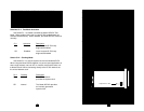
The G.703 Loop test allows the G.703 service provider to test the
condition of the twisted pair communication link between itself and the
Model 2070. Using this test, the service provider sends BER (Bit Error
Rate) signals to the Model 2070 over the twisted pair wire. The Model
2070 senses these signals and loops the digital data back to the central
office (Figure 16, below).
5.2.1 Test Mode Activation
1. Notify the G.703 Service provider that you wish to perform a
G.703 Loop test.
2. To Activate the Model 2070 Test Mode:
a. Move Switch S1-1 to the “ On “ position; OR,
b. Set Switch S1-4 to the Off (Enabled) position. Then
raise the appropriate “Loop Control” (LC) pin on the
terminal interface (see Appendix D).
When Test Mode is activated, both the Local Loop and G.703
Loop diagnostics are active: The terminal device’s transmitter
will be “looped” to its own receiver. Similarly, the G.703
transmitter output is connected to its own receiver input.
3. Perform a BER (bit error rate) test from the terminal interface.
If the BER test equipment indicates no faults, but the data
terminal indicates a fault, follow the manufacturer’s checkout
procedures for the data terminal. While the Test Mode is
activated, the TM light will illuminate Red.
4. The service provider may also perform a loop or BER test on
the G.703 communication link. If the loop or BER test
indicates a fault, the twisted pair connection may be faulty.
Model 2070
Figure 16 Test Mode Operation: Local Loop/G.703 Loop
Local
Loop
G.703
Loop
Digital Network


