


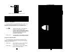

Jumper JP1: Power Source
The Model 2070/Cx may be powered by the V.35 interface or by
the supplied AC wall-mount transformer. The setting for JP1
determines how the Model 2070/Cx receives its operating power.
JP1
Position 1&2 Interface Power Option. In this setting the
2070/Cx Series unit is powered from the DTE
interface. Powered should be applied to M/34
pin KK at +5VDC (±5%), 300mA (min) The AC
wall-mount transformer must not be
connected in this setting.
Position 1&3 AC Power Option. In this setting, the 2070/Cx
is powered by the AC wall mount transformer
(default)
.
Jumper JP2: SGND & FRGND
In the default position, Signal Ground is connected to Frame
Ground. In the disconnected position, this strap disconnects Signal
Ground and Frame Ground.
Position 4&6 G.703 FRGND connected to DTE FRGND.
Both are disconnected from SGND
.
Position 5&6 G.703 FRGND connected to DTE FRGND
Both are connected to SGND
(default)
.
13
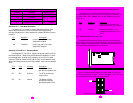
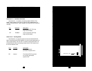
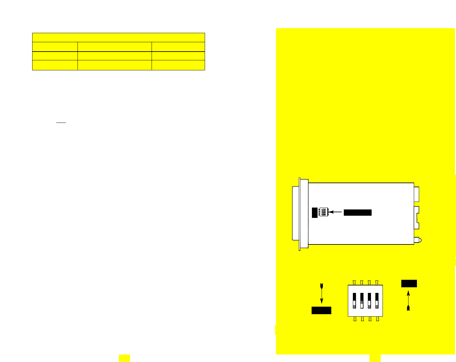
2070/Cx JP1 AND JP2 SUMMARY TABLE
Position Function Factory Default
JP1 Power Source 1&3 AC Powered
JP2 SGND to FGND 5&6 Connected
3.4 CONFIGURATION (MODEL 2070/Dx -- X.21 VERSION)
The Model 2070/Dx uses a mini DIP switch package and a jumper
strap that allow configuration to a wide range of applications. The
switch is located on the bottom side and the jumper strap is located on
the top side of the PC board. Follow the instructions below to configure
the 2070/Dx (X.21 Version). See Section 3.2 to configure the Model
2070/Ax (V.24 Version) or Section 3.3 to configure the Model
2070/Cx (V.35 Version).
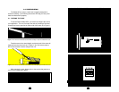
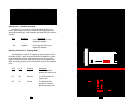
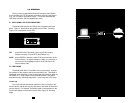
3.4.1 Configuration Switch Set “S1”
The four switches on DIP Switch S1 are used to select the test
mode and clock mode functions. Figure 11 shows the position of
Switch S1 on the bottom side of the Model 2070/Dx.
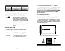
Figure 12 shows the orientation of the Switches on DIP Switch S1
with respect to ON/OFF positions. The default settings for DIP switch
S1 are shown in the table on the following page. Detailed descriptions
of each switch follow the table.
14
Figure 11. Location of Switch S1 on the bottom of the 2070/Dx PC board
ON
1234
Figure 12. Close-up of DIP Switches Showing “ON” and “OFF” Positions
ON
1234
OFF
ON
Switch S1
1234