


Pelco Manual C454M-C (1/98) 3
REVISION HISTORY
Manual # Date Comments
C454M — Original version.
C454M-A 6/95 Revised to incorporate B.O.M. quantity changes as per
ECO# 94-445. Added 4-position terminal block information
as per ECO# 94-042. Incorporated new “Front” labeling
to B.O.M. as per ECO# 94-192. Updated manual to new
style standards. Added manual revision history.
6/23/95 Addendum. Incorporated new fuse and fuse holder into
wiring diagrams and exploded view diagram as per
ECO# 95-063.
2/27/96 Addendum. Section 5.0 Mechanical Parts List revised.
C454M-B 4/96 Rev. B. Added Section 3.4.2.1 and Figure 16 per ECO#
96-061. Changed heater specifications.
C454M-C 1/98 Changed manual to new format and manual pagination.
Reduced number of models. Revised installation
instructions. Updated exploded assembly diagrams and
parts lists.
LIST OF ILLUSTRATIONS
Figure Page
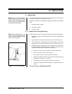
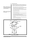
1 “T-Bar” Clip Installation .......................................................................9
2 Backup Plate Installation...................................................................11
3 24 VAC Back Box Wiring Diagram
(for Dome Drives with Integral Receiver/Driver) ................................14
4 120 VAC Back Box Wiring Diagram
(for Dome Drives with Integral Receiver/Driver) ................................15
5 230 VAC Back Box Wiring Diagram
(for Dome Drives with Integral Receiver/Driver) ................................16
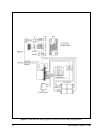
6 Wiring Diagram, Hard-Wire Control with Heater ...............................18
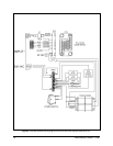
7 Wiring Diagram, Hard-Wire Control without Heater ..........................19
8 Suspended Ceiling Back Box Exploded Assembly Diagram.............21
9 Hard Ceiling Back Box Exploded Assembly Diagram .......................22
10 Pendant Back Box Exploded Assembly Diagram..............................23
11 Back Plate Exploded Assembly Diagram..........................................24
12 Suspended/Hard Ceiling Dimension Drawings .................................27
13 Pendant-Mount Dimension Drawing .................................................27
LIST OF TABLES
Table Page
A Video Coaxial Cable Requirements .................................................13
B 24 VAC Wiring Distances ..................................................................13
C Suspended Ceiling Back Box Exploded Assembly Parts List ...........21
D Hard Ceiling Back Box Exploded Assembly Parts List......................22
E Pendant Back Box Exploded Assembly Part List ..............................23
F Back Plate Exploded Assembly Parts List (Figure 11) ......................25