10 Pelco Manual C551M (4/98)
KBD9000
COAXITRON
®
RECEIVER
MULTICONDUCTOR
CABLE
VIDEO
SIGNAL
COAXITRON
®
RECEIVER
MULTICONDUCTOR
CABLE
VIDEO
SIGNAL
LOOPING
SWITCHER
KBD9000
TERMINATING
SWITCHER
COAXIAL
CABLE
MONITOR
(TERMINATED)
MONITOR
(TERMINATED)
COAXIAL
CABLE
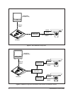
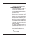
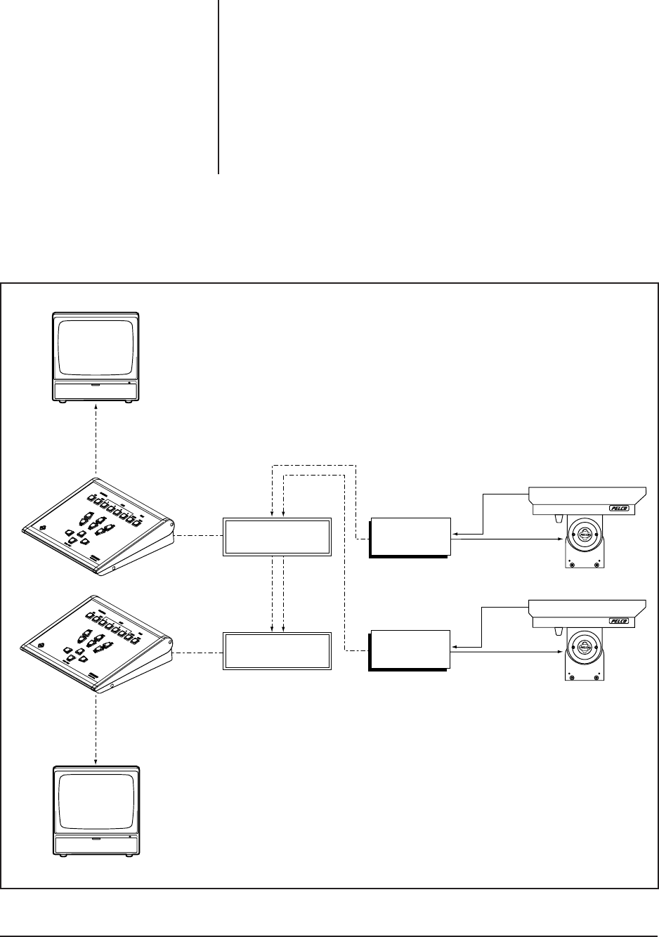
Figure 4. KBD9000 Configuration with Multiple Transmitters and Receivers
The Figure 4 drawing, KBD9000 Configuration with Multiple Transmitter and Re-
ceivers, shows a more complex system. In this example, multiple KBD9000 trans-
mitters are controlling multiple receivers.
Video cables from the receivers are looped through the first control station to the
second. At the first control station, a bridging-looping type sequential switcher is
used and the Hi-Z/75-ohm switch on the back of the KBD9000 is set to the Hi-Z
position. At the second control station, a terminating switcher is used and the Hi-Z/
75-ohm switch on the back of the KBD9000 is set to the 75-ohm position.
Any one KBD9000 transmitter can assume control. If two or more KBD9000 control
units are activated simultaneously, erroneous responses are prevented by error
detection circuitry in the associated receiver.
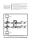
NOTE:
All but the last KBD9000
transmitter and associate switcher
must be looping and unterminated.
Transmitters and associated
switchers should be physically ad-
jacent to prevent signal deteriora-
tion due to cable mismatch.


