English
8 PRODUCT DESCRIPTION
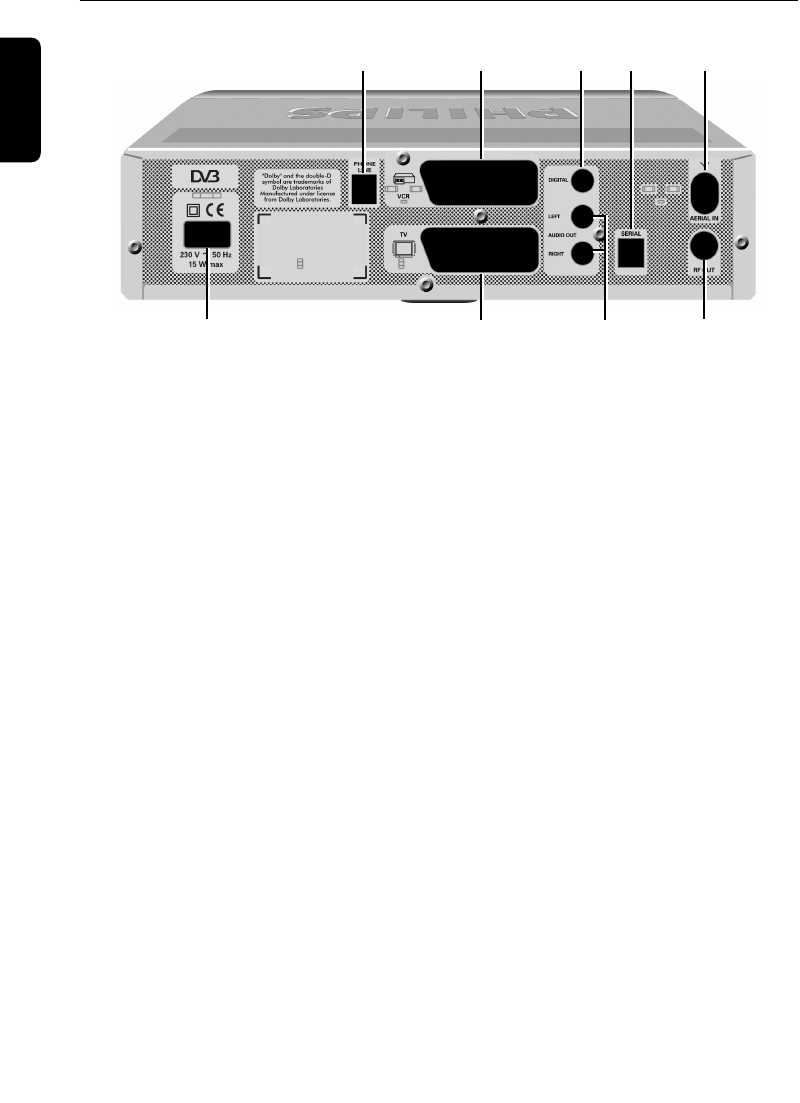
1.2 Rear view
1 Telephone Line*** To connect the supplied telephone cord to be connected to
your telephone line using the appropriate adapter (adapter
not supplied).
2
VCR SCART* (1) To connect a SCART lead to be connected to the SCART
socket input (EXT1) of your VCR or DVD Recorder.
3 Digital Audio* To connect to one of the digital audio input of your HiFi /audio
receiver system.
4 Serial* Data interface used during servicing.
5 Aerial In* To connect the plug of your aerial cable.
6 230V~50Hz 15W max.** To connect the supplied mains cord to be connected to the
power socket.
7
TV SCART* (1)(2) To connect the supplied SCART lead to be connected to the
SCART socket input of your TV set.
8 L/R Audio Output* To connect to the Left/Right audio Cinch inputs of your
HIFI/audio receiver system.
9 RF Out* To connect the supplied RF coaxial cable to be connected to
the aerial input socket of your TV or VCR.
* SELV: Safety Extra Low Voltage.
** HV: Hazardous Voltage.
*** TNV 3: Telecommunication Network Voltage 3.
(1) SCART is also called Euroconnector or Peritel.
(2) The supply SCART lead is suited for RGB format which allows the best picture quality. Consult the
user manual of your TV set to select its RGB capable SCART socket input.
Note: The label showing the type and the serial number is underneath your receiver.
6789
12345
6610_A5_GB.qxd 01/09/2004 12:58 Page 8


