


3139 246 13521
English
7
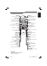
Connections
COAXIAL OPTICAL
DIGITAL AUDIO OUT
PCM/MPEG2/Dolby Digital
CVBS
S-VIDEO
Y
Pb
Pr
STEREO
FRONT
W
L
R
L
R
AUDIO
IN
V (Pr/Cr)
U (Pb/Cb)
Y
S-VIDEO
IN
VIDEO IN
COMPONENT
VIDEO IN
AUDIO
OUT
V (Pr/Cr)
U (Pb/Cb)
Y
S-VIDEO
IN
VIDEO IN
COMPONENT
VIDEO IN
2
1
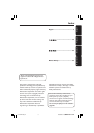
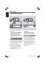
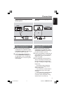
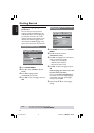
IMPORTANT!
– Component Video connection
provides higher picture quality. This
option must be available on your TV.
– The progressive scan video
quality is only possible through
Component Video (Y Pb Pr) output.
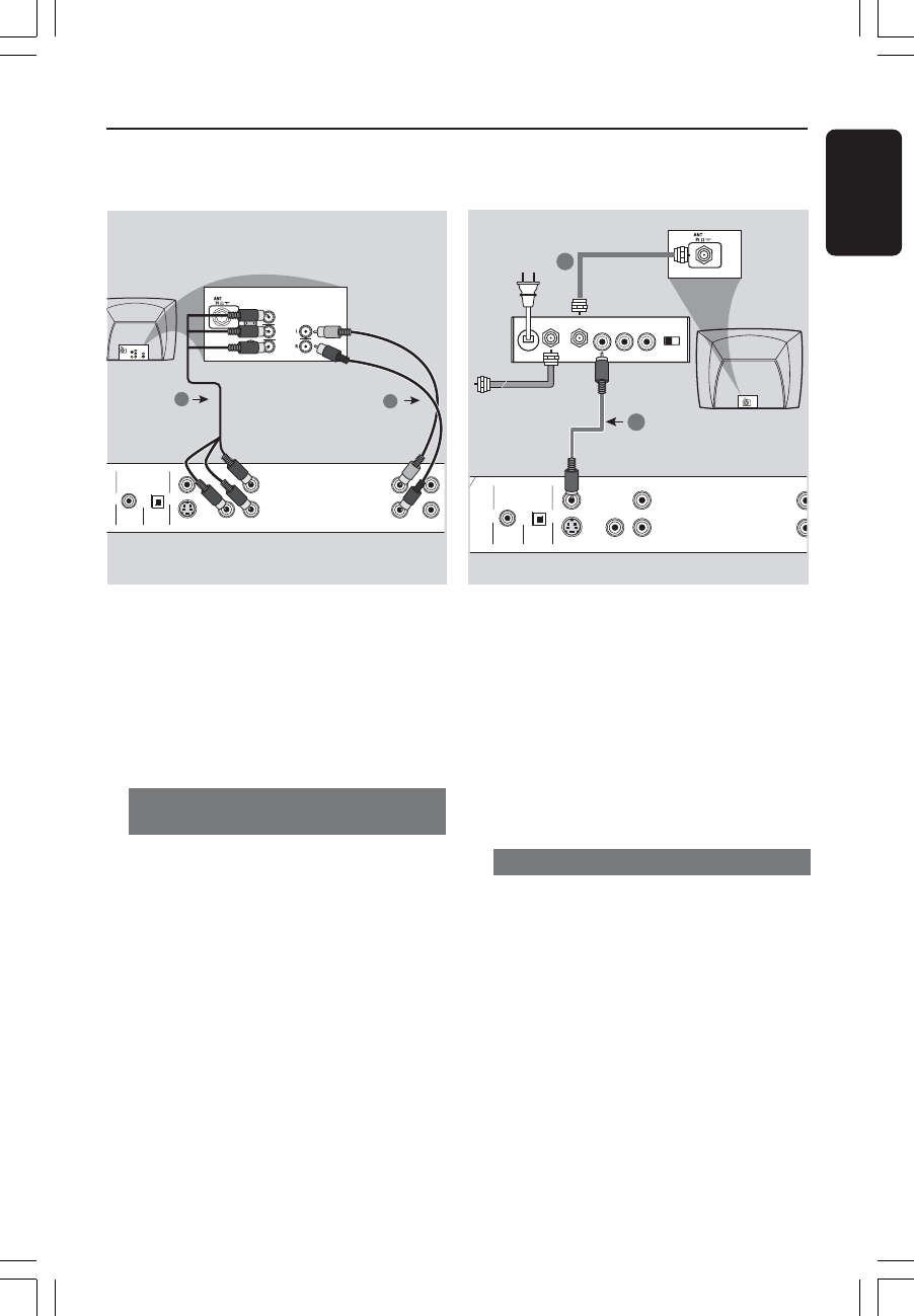
Using Component Video jacks
(Y Pb Pr)
1 Use the component video cables (red/
blue/green) to connect the DVD system’s
Y Pb Pr jacks to the corresponding
Component video input jacks (or labeled
as Y Pb Pr) on the TV (cable not supplied).
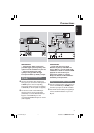
2 To hear the sound of this DVD Player
through your TV, use the audio cables
(white/red) to connect AUDIO OUT (L/
R) jacks of the DVD Player to the
corresponding AUDIO IN jacks on the TV
(cable supplied).
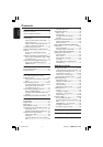
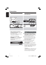
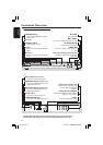
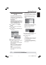
IMPORTANT!
– If your TV only has a single
Antenna In jack (or labeled as 75
ohm or RF In,) you will need an RF
modulator in order to view the DVD
playback on the TV. See your
electronics retailer or contact
Philips for details on RF modulator
availability and operations.
Using an accessory RF modulator
1 Use the composite video cable (yellow) to
connect the DVD Player’s CVBS jack to
the video input jack on the RF modulator.
2 Use the RF coaxial cable (not supplied) to
connect the RF modulator to your TV’s
RF jack.
COAXIAL OPTICAL
DIGITAL AUDIO OUT
PCM/MPEG2/Dolby Digital
CVBS
S-VIDEO
Y
Pb
Pr
STER
L
R
AUDIO IN
R L
VIDEO
IN
TO TVINT IN
CH3 CH4
2
1
RF coaxial cable to TV
Back of RF Modulator
(example only)
Antenna or
Cable TV signal
01-34 DVP720_AP 18/03/2004, 10:38 AM7