


English
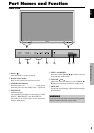
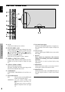
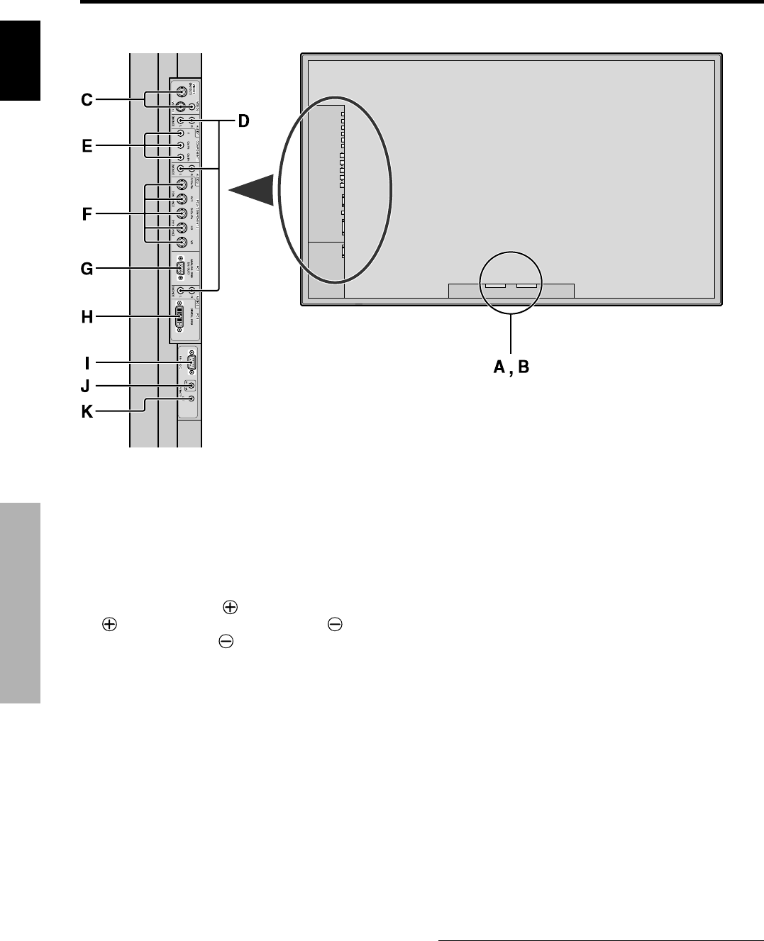
Part Names and Function
6
En
A AC IN
Connect the included power cord here.
B EXT SPEAKER L and R
Connect speakers (optional) here. Maintain the correct
polarity. Connect the
(positive) speaker wire to the
EXT SPEAKER terminal and the (negative)
speaker wire to the
EXT SPEAKER terminal on
both LEFT and RIGHT channels.
Please refer to your speaker’s owner’s manual.
C VIDEO1, 2, 3 (BNC, RCA, S-Video)
Connect VCR’s, DVD’s or Video Cameras, etc. here.
VIDEO1 can be used for Input or Output (see page
24).
D AUDIO1, AUDIO2, AUDIO3
These are audio input terminals.
The input is selectable. Set which video image to allot
them from the SOUND menu screen.
E COMPONENT1
Connect DVD’s, High Definition or Laser Discs, etc.
here.
F PC2/COMPONENT2
PC2: You can connect an analog RGB signal
and the syncronization signal.
COMPONENT2
: You can connect DVDs, High
Definition sources, Laser Discs, etc.
here.
This input can be set for use with an
RGB or component source (see page
17).
G PC1 (mini D-Sub 15pin)
Connect an analog RGB signal from a computer, etc.
here. This input can be used for Input or Output (see
page 24).
H PC3
(DVI 24pin)
Connect a digital signal (TMDS) from a source with a
DVI output.
I RS-232C
Never connect any component to this connector
without first consulting your Pioneer installation
technician.
This connector is used for plasma display setup
adjustments.
J REMOTE IN
Connect the remote cable* to the remote control’s
remote jack to obtain wired remote control.
K REMOTE OUT
Connect the remote cable* to the REMOTE IN jack of
the other display monitor to obtain wired remote
control.
* The 1/8 Stereo Mini cable must be purchased separately.
Rear View/ Terminal Board