


English
OSD (On Screen Display) Controls
17
En
Option1 Settings Menu
Setting the on-screen display
This sets the position of the menu, the display format
(horizontal or vertical) etc.
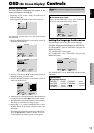
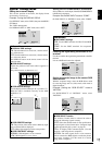
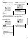
Example: Turning the DISPLAY OSD off
On “OPTION1” menu, select “OSD”, then press the MENU/
SET button.
The “OSD” menu appears.
On “DISPLAY OSD” of “OSD” menu, select “OFF”.
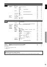
OSD
DISPLAY OSD
OSD ADJUST
OSD ANGLE
OSD ORBITER
OSD CONTRAST
: OFF
: 1
: H
: OFF
: LOW
SEL.
ADJ.
EXIT RETURN
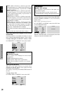
Information
Ⅵ DISPLAY OSD settings
ON: The informations on screen size, volume control,
etc. will be shown.
OFF: The informations on screen size, volume control,
etc. will not be shown.
The DISPLAY button on the remote control will not
function either.
Ⅵ OSD ADJUST settings
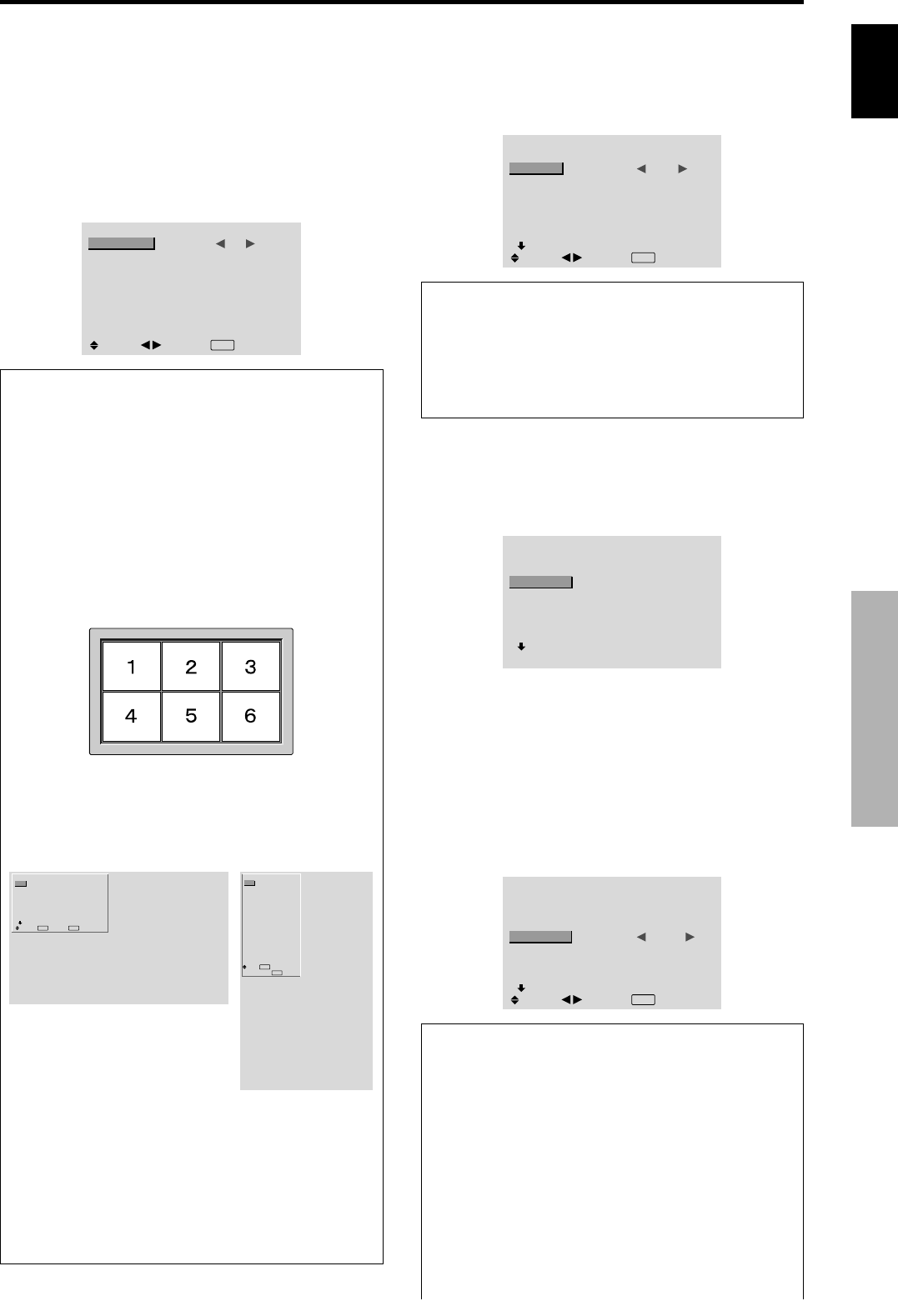
Adjusts the position of the menu when it appears on
the screen.
The position can be set between 1 to 6.
Ⅵ OSD ANGLE settings
Sets the display format (landscape “H” or portrait “V”).
When the unit is installed vertically set the OSD
ANGLE at “V”.
“H”“V”
Ⅵ OSD ORBITER settings
ON: The position of the menu will be shifted by eight
dots each time OSD is displayed.
OFF: OSD will be displayed at the same position.
Ⅵ OSD CONTRAST settings
NORMAL: OSD brightness is set to normal.
LOW: OSD brightness is set to lower.
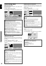
Setting the PC2/COMPONENT2 connectors
Select whether to set the input of the PC2/COMPONENT2
to RGB and component.
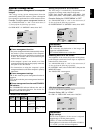
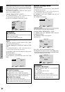
Example: Set the BNC INPUT mode to “COMP.”
On “BNC INPUT” of “OPTION1” menu, select “COMP.”.
OPTION1
1 / 3
OSD
BNC INPUT
D-SUB INPUT
RGB SELECT
HD SELECT
INPUT SKIP
ALL RESET
NEXT PAGE
: COMP.
: RGB
: AUTO
: 1080B
: OFF
: OFF
SEL.
ADJ.
EXIT RETURN
Information
Ⅵ BNC INPUT Settings
RGB: Use the 5BNC terminals for HD, VD and RGB
signals.
COMP.: Use the 3BNC terminals for component
signals.
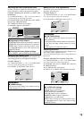
OPTION1
1 / 3
OSD
BNC INPUT
D-SUB INPUT
RGB SELECT
HD SELECT
INPUT SKIP
ALL RESET
NEXT PAGE
: RGB
: RGB
: AUTO
: 1080B
: OFF
: OFF
SEL.
EXIT RETURNOK
MENU
OPTION1
OSD
BNC INPUT
D-SUB INPUT
RGB SELECT
HD SELECT
INPUT SKIP
ALL RESET
: RGB
: RGB
: AUTO
: 1080B
: OFF
: OFF
1024768
SEL.
EXIT RETURN
OK
MENU
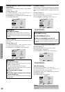
Checking the signal being transmitted to PC1
terminal
Use this to confirm the signal being transmitted to the PC1
terminal.
It is set to RGB and can not be adjusted.
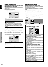
OPTION1
1 / 3
OSD
BNC INPUT
D-SUB INPUT
RGB SELECT
HD SELECT
INPUT SKIP
ALL RESET
NEXT PAGE
CAN NOT ADJUST
: RGB
: RGB
: AUTO
: 1080B
: OFF
: OFF
Setting a computer image to the correct RGB
select screen
With the computer image, select the RGB Select mode
for a moving image such as (video) mode, wide mode or
digital broadcast.
Example: Setting the “RGB SELECT” mode to
“MOTION ”
On “RGB SELECT” of “OPTION1” menu, select
“MOTION”.
OPTION1
1 / 3
OSD
BNC INPUT
D-SUB INPUT
RGB SELECT
HD SELECT
INPUT SKIP
ALL RESET
NEXT PAGE
: RGB
: RGB
: MOTION
1024
×
768
: OFF
: OFF
SEL.
ADJ.
EXIT RETURN
Information
Ⅵ RGB SELECT modes
One of these 8 modes must be selected in order to
display the following signals correctly.
AUTO: Select the suitable mode for the specifications
of input signals as listed in the table “Computer input
signals supported by this system” on page 29.
STILL: To display VESA standard signals. (Use this
mode for a still image from a computer.)
MOTION: The video signal (from a scan converter)
will be converted to RGB signals to make the picture
more easily viewable. (Use this mode for a motion
image from a computer.)