


LC640.480.33-AC Operations Manual (OM600-01)8
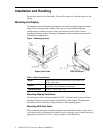
Interfacing and Operation
Control Basics
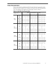
Power Requirements
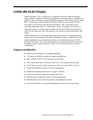
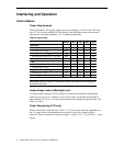
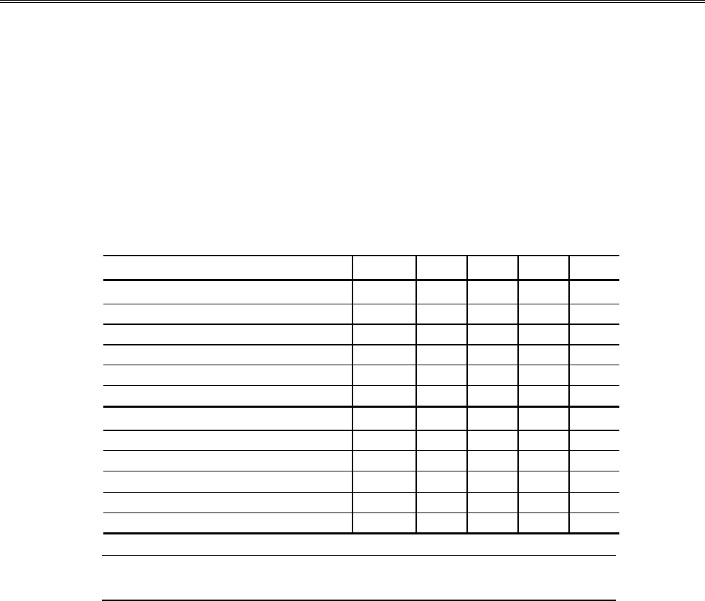
The LC640.480.33-AC display requires two power supplies: +5 Vdc for the LCD logic
and +12 Vdc for the backlight. In Table 6 below, the backlight current and power are
referenced to maximum luminance, 25 °C ambient temperature.
Table 6. Input Power
Symbol Min Typ Max Units
Backlight
Backlight voltage V
H
+10.8 +12.0 +13.2 Vdc
Absolute max. voltage V
HMAX
0 – +16 Vdc
Steady state current (V
H
= +12 Vdc) I
H
– 1.9 2.5 Adc
Peak start-up current (V
H
= +12 Vdc) I
HSU
– – 3.5 Adc
Power (V
H
= +12V) P
H
– 23 30 W
LCD
LCD voltage V
L
4.5 +5.0 +5.5 Vdc
Absolute max. voltage V
LMAX
0 – 6.0 Vdc
V
L
permissible ripple (V
L
= +5V)
∆V
L
– – 100 mVpp
Current (V
L
= +5V) I
L
– 280 450 mAdc
Power (V
L
= +5V) P
L
– 1.4 2.3 W
CAUTION: Absolute maximum ratings are those values beyond which damage to
the device may occur.
Undervoltage Lockout (Backlight only)
An undervoltage lockout (UVLO) function is included which disables the backlight
under excessively low V
H
conditions. The UVLO circuit will disable the backlight at
approximately +8.5 Vdc as V
H
falls and will enable the backlight at approximately +9.5
Vdc as V
H
rises.
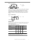
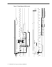
Power Sequencing (LCD only)
Certain restrictions on the behavior of the V
L
(+5 Vdc) source and in the application of
the V
L
source relative to the application or removal of the video signals must be
observed. These restrictions are shown in Figure 2, where “Vcc”= V
L
and “data” = video
signals.