


LC640.480.33-AC Operations Manual (OM600-01)10
Video Signals
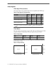
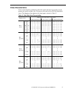
Video Signal Characteristics
Video signal inputs on J3 are digital inputs and are compatible with CMOS logic.
Table 8. Video Signal DC Characteristics.
Description Symbol Minimum Maximum Units
Absolute Maximum Input Voltage V
I
max
-0.3 V
L
+ 0.3 Vdc
Low-level Input Voltage V
IL
0 0.3V
L
Vdc
High-level Input Voltage V
IH
0.7V
L
V
L
Vdc
Low-level Input Current
1
I
IL1
– 1 µA
I
IL2
– 60 µA
High-level Input Current
2
I
IH1
– 1 µA
I
IH2
– 60 µA
1. I
IL1
applies to all signals except R/L and U/D. I
IL2
applies to signals R/L and U/D.
2. I
IH1
applies to all signals except ENAB, U/D, and R/L. I
IH2
applies to signals ENAB, U/D,
and R/L.
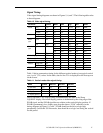
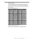
Video Modes
The video interface automatically recognizes 480-, 400-, and 350-line formats. Mode
recognition depends on the polarity of the sync signals as shown in Table 9.
Table 9. Video Modes.
Mode 480 line 400 line 350 line
Hsync (J3-3) negative negative positive
Vsync (J3-4) negative positive negative
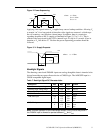
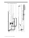
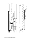
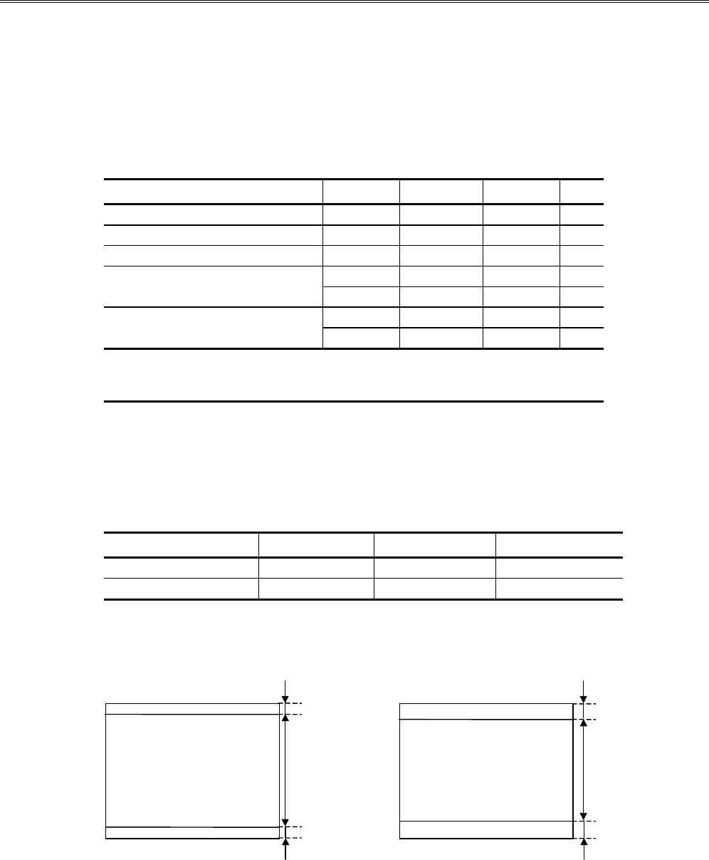
In 400-line and 350-line modes, the screen image will be automatically centered as
shown in Figure 4 below.
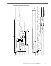
Figure 4. Image centering.
data period
data invalid period
data invalid period
40 lines
40 lines
400 lines
400 lines mode (TV=449)
data period
data invalid period
data invalid period
65 lines
65 lines
350 lines
350 lines mode (TV=449)