


LC640.480.33-AC Operations Manual (OM600-01)20
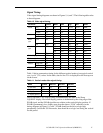
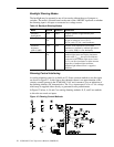
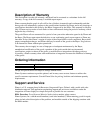
Backlight Dimming Modes
The backlight may be operated in one of four modes without the use of jumpers or
switches. The mode is selected based on the state of the /ABCOFF input and on whether
the dimming input is left open or connected to a voltage source.
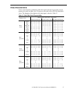
Table 16. Backlight Dimming Modes.
Mode VRLUM /ABCOFF Comments
Extended
backlight life
open GND Display operates at approximately half
luminance.
Manual dimming Rpot or
Vin
GND Minimum-to-maximum luminance as defined
by pot or voltage at V
RLUM
(J2-2):
0 Vdc = min, +5 Vdc = max luminance
Automatic
brightness
control (ABC)
open open Default mode. Minimum-to-maximum
luminance as defined by ambient light sensor:
0 lx = min, 3000 lx = max luminance.
Biased ABC Rpot or
Vin
open Combination of dimming control and
ambient light sensor sets display luminance.
In this mode, V
RLUM
has twice the influence
compared to the ambient light sensor, hence
V
RLUM
can drive luminance to either extreme
regardless of ambient light conditions.
Ambient light influence max is capped at
3000 lux.
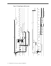
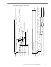
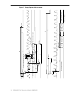
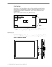
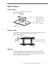
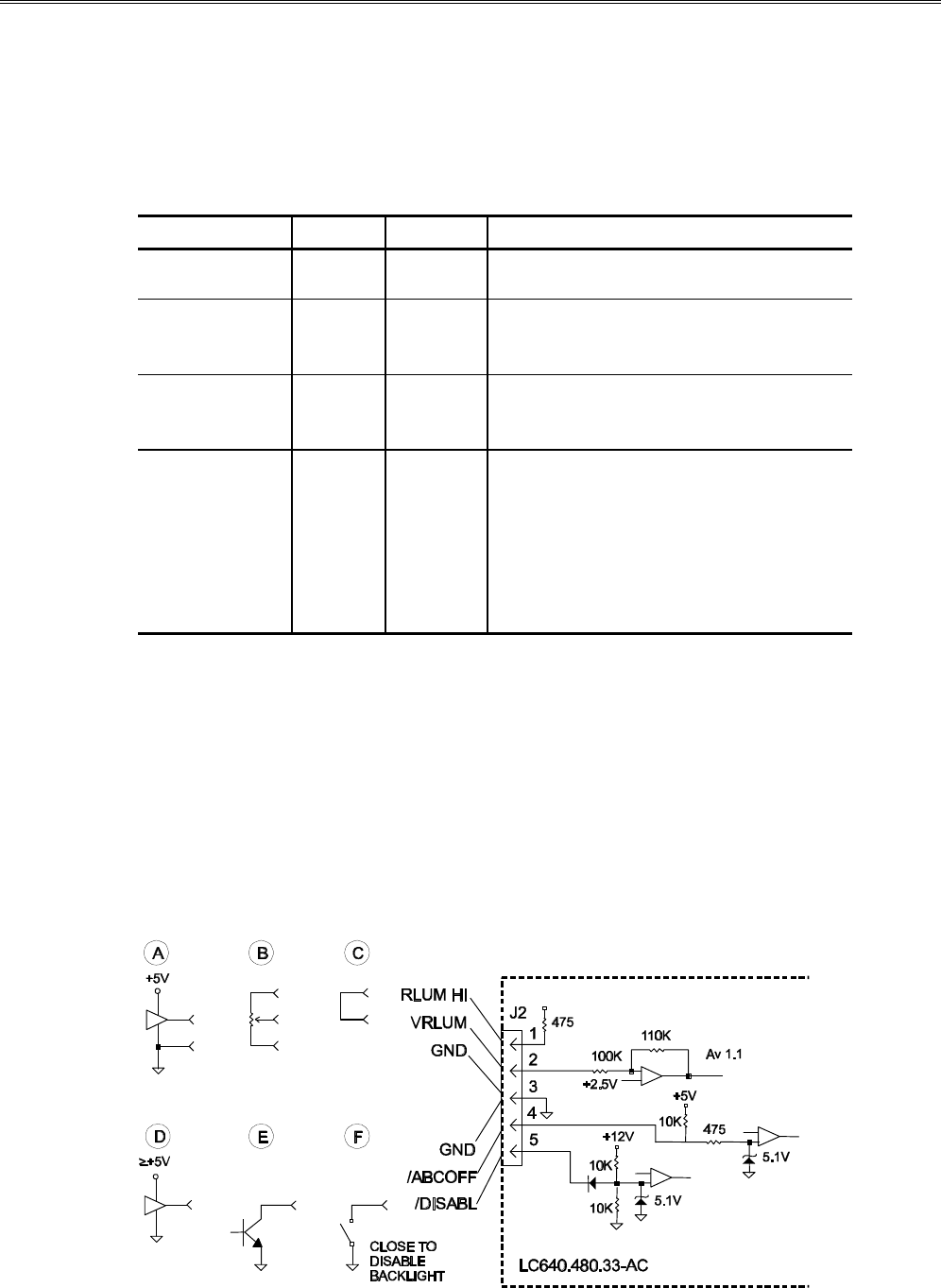
Dimming Control Interfacing
An analog dimming control is available on J2. Some common methods to use this input
are shown in Figure 12. In this figure, the schematic shown is an approximation of the
circuitry actually present in the LC640.480.33-AC and is meant to give an indication of
the dimming interface DC characteristics. The V
RLUM
input expects a 0 to +5 Vdc voltage
which may be supplied either directly or generated from a potentiometer.
In Figure 12 below, A, B, and C are analog dimming methods. D, E, and F are methods
to drive the two mode set inputs.
Figure 12. Dimming Control Methods.