


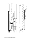

LC640.480.33-AC Operations Manual (OM600-01)18
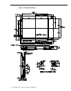
Dimming Connector (J2)
A dimming voltage or potentiometer, plus optional backlight mode and disable logic
inputs are applied via J2, which is a polarized 5-pin inline, 2.5 mm pitch header, tin
plated with a friction lock. The connector is equivalent to the Molex 5268-NA ‘SPOX’
series, part number 22-05-7055. The recommended mating connector is a Molex 5264-N
series housing, part number 50-37-5053 and Molex 5263 series crimp pin, part number
08-70-1040. The recommended wire size is 22-28 AWG stranded. Refer to on page 19
for more information.
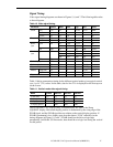
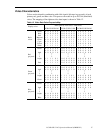
Table 14. Dimming Connector (J2) Pinouts.
Pin Symbol Function
1 RLUM HI Pot high side voltage source output
2 VRLUM Analog dimming input
3 GND Signal ground (return)
4 /ABCOFF Automatic brightness control mode
disable input
5 /DISABL Backlight disable input
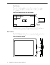
Backlight Power Connector (J1)
Backlight power (V
H
) is applied via J1, which is a polarized 3 pin, 3mm pitch header
with gold plated (15µ") contact surfaces and a release latch. J1 is equivalent to a Molex
43650-0301 (“Micro-Fit 3.0” series). The recommended mating connector is a Molex
part number 43645-0300 (housing) and Molex part number 43030-0008 (crimp pin). The
recommended wire size is 20 AWG stranded.
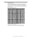
Table 15. Backlight Power Connector (J1) Pinouts.
Pin Symbol Function
1 GND Power ground
2 V
H
Backlight power
3 GND Power ground
Note: Power Ground (GND) is isolated from the display metal bezel. All signals
and power on the backlight are also isolated from the J3-related AMLCD display
circuits.