4
Table of Contents
1. Specifications ...................................................................................................................................... 5
2. Operation............................................................................................................................................ 7
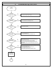
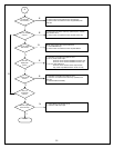
3. Troubleshooting Flow Chart................................................................................................................ 13
4. Polaroid Display Cell Defect Specification ............................................................................................ 15
5. Before Returning This Product to the User .......................................................................................... 16
6. Disassembly Procedure ...................................................................................................................... 17
Rear Cover Removal...................................................................................................................... 18
Main Board Removal and Replacement ........................................................................................... 20
Control Button Board Removal and Replacement............................................................................. 22
DVD Module Board Removal and Replacement................................................................................ 23
Power Board Removal and Replacement......................................................................................... 24
IR / Power LED Board Removal and Replacement ........................................................................... 25
7. Spare Parts List – FXM-2611C............................................................................................................. 26
8. Exploded View Diagram – FXM-2611C................................................................................................. 27
9. Block Diagrams – FXM-2611C............................................................................................................. 28
10. Schematic Diagrams – FXM-2611C...................................................................................................... 30
11. PCB Layout Diagrams ........................................................................................................................ 38


