1-6
IINNSSTTAALLLLAATTIIOONN ((ccoonnttiinnuueedd))
RGB Signal Input:
Connect the RGB IN terminal of the projector to the display signal output of the computer by the
enclosed RGB cable. Secure the screws on the connector and tighten.
For some modes, the enclosed Mac adapter is necessary. Refer to the “Table 1-8. Example of
Compatible Computer Signal” of the section “SPECIFICATION”.
NOTE: Some computers may have multiple display screen modes. Use of some of these modes will
not be possible with this projector.
Video Signal Input:
Connect the VIDEO terminal of the projector to the video signal output of the video tape recorder
by the enclosed video cable except for S-Video signal.
For S-Video signal, use the S-VIDEO terminal of the projector and the optional cable for S-Video.
Audio Signal Input:
Connect the AUDIO IN terminal of the projector to the audio signal output by the enclosed audio
cable.
RS232C:
Connect the CONTROL terminal of the projector to the computer.
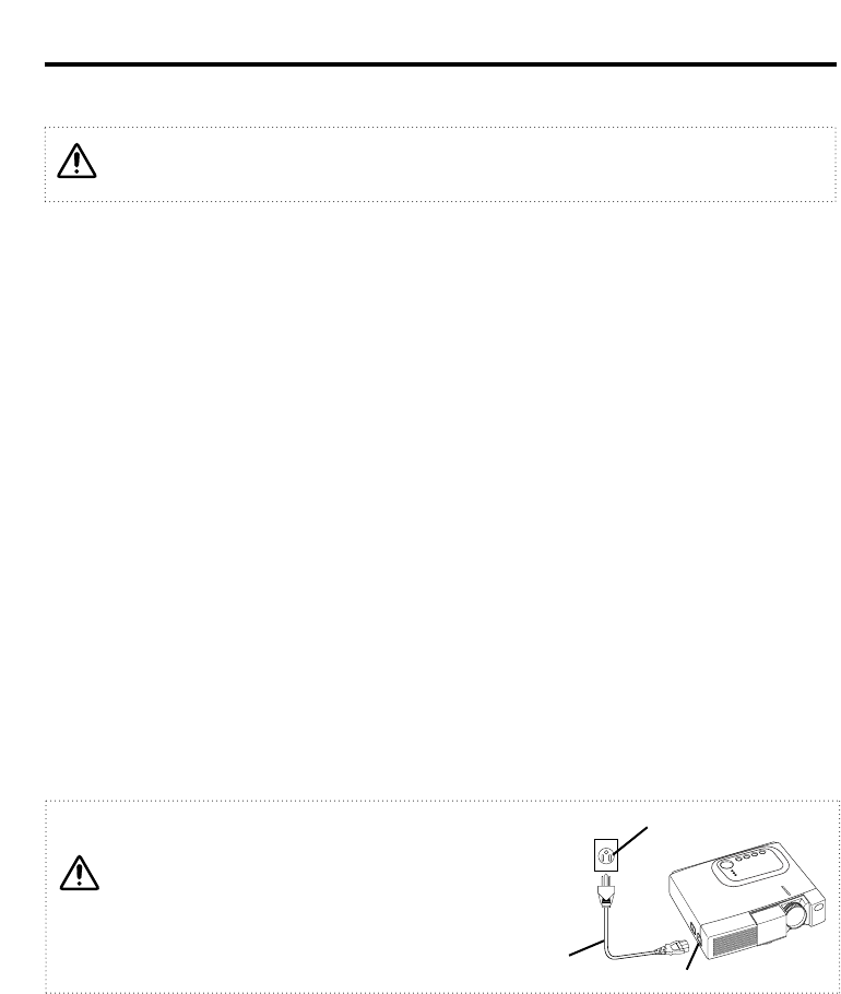
Power Connection:
Use the correct one of the enclosed power cords depending on the power outlet to be use.
Connect the AC inlet of the projector to the power outlet firmly by the power cord
Cabling
Before connecting, read the instruction manuals of the devices to be connected, and make
sure that the projector is compatible with the device, and turn off to all devices to be
connected.
WARINING
Be carful in handling the power cord according to
instructions of the accompanying manual "SAFETY
INSTRUCTIONS" and this manual.
Connect the power cord firmly. Avoid using a loose,
unsound outlet or contact failure.
AC INLET
Power Cord
Power outlet


