


Page 6 Installation Instructions
LPFM1532
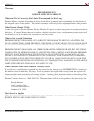
Universal Spacers Installation
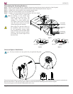
Determining the Mounting Hardware
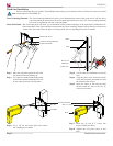
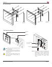
Step 1. Insert the thread depth indicator (supplied) through the thread inserts found on the back of the flat panel.
Step 2. Using a pencil, mark the depth of the thread insert on the thread depth indicator (Figure 2).
Step 3. Compare and verify the depth of the remaining thread inserts.
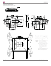
Step 4. Locate the correct diameter screw for the thread insert.
Step 5. Compare your thread depth indicator marking to the screw length.
Figure 1
Figure 2
Figure 3
Inverted Flat
Panel Display
Marking the
Depth
Thread Insert
Thread Depth
Indicato
r
Thread Depth
Indicator
Marking
Scre
w
Marking
Screw
Thread Depth
Indicato
r
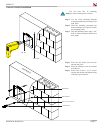
When using the universal spacers in
the installation, make sure to account
for the appropriate spacing depth
when measuring with the thread depth
indicator. Using the universal spacers
will change the overall length of the
hardware used.
If your selected screw is longer than
the marking on the thread depth
indicator, do not use this screw. The
screw length must not bypass the
marking. If so, select another screw
size (Figure 2 and 3) until you find the
screw the comes closest to your mark
without going past the marking.
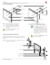
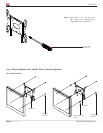
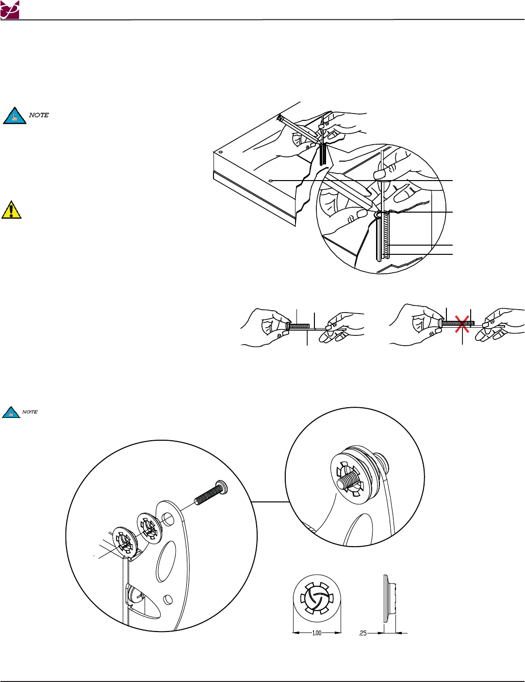
The universal spacer may be stacked five (5) high, for a total stacking height of 1-1/4”. The universal spacers must be stacked in the
direction shown above. The universal spacers must be placed between the mounting bracket and the flat panel.
The universal spacer will fit M4, M5, M6 and M8 screws sizes.
You may not need to use any spacers for your particular flat panel.