


PWM-F110
Page - 11 - Installation Manual
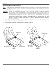
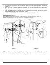
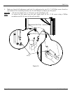
3. To connect the two wall plates, lay them on a flat surface, end to end. Make sure that the holes line up
(Figure 11).
4. Insert two (2) M8 x 16mm Hex Head bolts through the two holes and secure with two (2) M8 Hex nuts
(Figure 11).
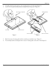
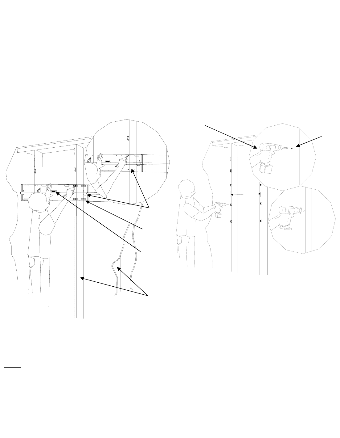
5. Place the bottom portion of the wall plate to the reference line and mark the eight (8) lag bolt
mounting points through the wall plate slots on the wall.
6. Level the wall plate with the reference arrow pointing up to the ceiling (Figure 11).
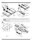
Mounting Surfaces (Figure 14)
Wood studs: Drill eight (8) ¼" pilot holes to the marked wall (16”studs, on center – Figure 12).
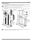
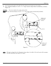
Concrete wall: Drill eight (8) 3/8” pilot holes to the marked wall (Figure 18).
16"
Figure 11 Figure 12
NOTE
: Although not depicted in the illustrations shown above, the width of this wall mount will
encompass four wall studs (three wall studs if 24” apart).
Wood Studs
Level
Mounting
Slots
Wall Plate
Drill Gun
Pilot
H
oles