


6
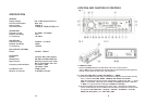
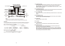
19. CLOCK BUTTON
Press the CLK button briefly to display time on the display, then press
the CLK button and hold until the real time flashes on the display.
Rotate the VOL +/- knob left to adjust HOUR. Rotate the VOL +/- knob
right to adjust MINUTE.
20. LOUDNESS BUTTON
Press the LD button to enhance the bass effect when the volume level is
low. Press again to cancel the loudness effect.
21. ST/MO BUTTON
During radio mode, press the ST briefly to select stereo or mono sound
mode.
22. RELEASE BUTTON
To remove the front control panel from the main body, press the REL
button to eject the front control panel.
23. EJECT KEY
Press this key to eject the CD.
24. CD SLOT
25. FLASHING LED
When the front control panel is removed this indicator flashes.
26. RESET BUTTON
Push this button with a cuspidal object to renovate the distorted
program once the program is distorted.
Note: Before operating the unit for the first time, or after replacing
the car battery or changing the connections. You must reset the unit.
Push this button with a cuspidal object. This operation will erase the
clock setting and some stored contents.
9
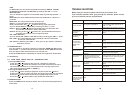
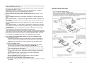
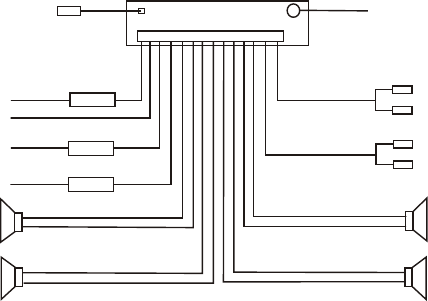
VFD TRANSFORMER
Note:
1.Make sure use a speaker with 4 ohm load impedance.
2.Do not make the auto antenna wire and ground touch each other.
+
+
+
+
FUSE 10A
YELLOW
ANTENNA PLUG
CONSTANT B+
BLACK(GND)
ACC RED (B+)
FRONT
REAR
RIGHT
FRONT
WHITE
WHITE/BLACK
GREEN/BLACK VIOLET/BLACK
GREY/BLACK
GREY
VIOLET
GREEN
REAR
LEFT
LOUDSPEAKER
FUSE 0.5A
-
-
-
-
BLUE AUTO ANT
RCA OUTPUT LINE
RED R
WHITE L
FUSE 0.5A
LOUDSPEAKER
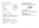
WIRING DIAGRAM
CAUTION:
In order to protect power IC from being burnt out during installation the car stereo,
it is necessary to follow the steps below to connect the wires during installation:
Step 1: Connect the ground wire (Black);
Step 2: Connect all speaker wires and power antenna wire (Blue):
Left speaker Right speaker
Front speaker: White (+) White/Black (-)
Rear speaker: Violet (+) Violet/Black (-)
Step 3: RCA Line Out (R- Red/ L-White).
Grey (+) Grey/Black (-)
Green (+) Green/Black (-)
Step 4: AUX Line in ( R-Red/L-White).
Note: This AUX Line in for video system audio input.
Step 5: Connect Back up (Yellow) and Acc wire (Red)
RED R
WHITE L
AUX LINE IN