


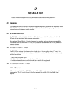
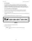
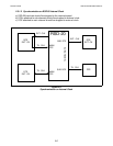

2.4.2 Rear Panel
Six connectors are located on the rear panel of the RSD-20, consisting of five channel
connectors (four for the sub-channels and one for the main channel) and one 3-pin power
connector, which also includes the fuse holder. The five channel connectors are 34-pin
connectors for the V.35 interface or 15-pin, D-type for the X.21 interface. The ON/OFF power
switch and the 110/220 VAC selection switch are located also on the rear panel (see Figure 2.1).
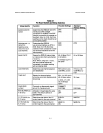
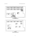
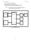
2.4.3 Internal Switches and Strap Selection
The internal switches and straps on the RSD-20 should be configured to meet system
requirements. In order to change the settings, the following steps should be followed:
a) Disconnect the AC power cable.
b) Remove the RSD-20 top cover, loosen the two screws on the rear panel and slide back the top
cover.
c) Identify the straps according to Table 2.1 and Figures 2.3 and 2.4.
d) Install the straps/switches in the required position.
e) Reinstall the top cover.
CAUTION Disconnect the instrument from the input line power before removing
covers.
MAIN CHANNEL SUB CHAN. 1SUB CHAN. 2SUB CHAN. 3SUB CHAN. 4
POWER
~230V
~115V
F-0.400A S.B.
Figure 2.1
Rear Panel
INSTALLATION RSD-20 OPERATOR'S MANUAL
2.2