


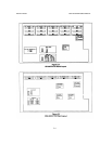
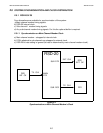
2.5.2.4 Main channel is DCE and sub-channels are mixed
(DTE and DCE)
In this mode one of the modems attached to the sub-channels (configured as DTE) should be
attached to sub-channel 1, and the RSD baud rate should be strapped to CLK-1.
The DTEs attached to the main and sub-channels are synchronized to the RSD’sclock;the
modems attached to the sub-channels are synchronized to their own clock; and the internal
buffer compensates for the phase difference between the signal timing of the modem attached to
sub-channel 1 to the rest of the modems.
NOTE 1. Working with RSD’s internal clock is also possible but CLK-1 is
preferred.
2. On DTE (sub-channels 1 to 4 and Main channel), the RSD-20 supplies
clock on pins 7 and 14 for DCE external clock (The DCE must support
external clock as in the ASM-20/8-X.21).
WARNING Before plugging in this unit, the protective ground (earth) terminals must
be connected to the protective conductor of the (mains) power cord. The
mainsplugshouldonlybeinsertedinasocketoutletprovidedwitha
protective ground (earth) contact. The protective action must not be
negated by use of an extension cord (power cable) without a protective
conductor (grounding).
Ensure that only fuses with the required rated current, and specified type
(slow blow, 0.4A) are used for replacement. The use of repaired fuses,
and the short-circuiting of fuse holders is strictly forbidden.
Whenever it is likely that the protection offered by fuses has been
impaired, the instrument must be made inoperative and secured against
unintended operation.
With the unit power turned on, operating personnel are not exposed to
voltages in excess of 30 volts on any I/O pin, provided that the equipment
to which the RSD-20 is connected is safe.
RSD-20 OPERATOR'S MANUAL INSTALLATION
2.9