


3.4 OPERATIONAL FIELD STRAPPING CHANGES
Access inside the equipment is only permitted to authorized service personnel.
If it becomes necessary to reconfigure the RSD-20 for a different type of operation, the internal
straps must be changed to correspond to the new operating mode. For guidance in repositioning
the straps, refer to the information given in Chapter 2 of this manual. It is recommended that the
straps be changed by an experienced technician.
CAUTION Do not open the top cover for strap changes before removing the AC
power from the unit.
3.5 FAULT ISOLATION PROCEDURE
WARNING These service instructions should be used by qualified personnel only.
Access inside the equipment is only permitted to authorized service personnel.
3.5.1 Power Supply
If AC power has been applied to the RSD-20 but the green power LED does not light up, check
installation according to the following procedure:
a) Verify that the 110/220 selector is set correctly.
b) Verify that the power switch light is on.
c) Unplug the AC cord and then pull out the fuse (located above 3-pin power connector). Check
the fuse and replace if necessary (0.4A S.B.).
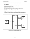
d) Remove the top cover of the unit and check that the 5-pin power connector (connecting the
secondary wires of the transformer to the main card) is connected properly.
3.5.2 RSD Malfunction
If the Power LED is ON but the RSD-20 is not functioning in the system, proceed as follows:
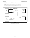
a) Unplug the AC cord and remove the top cover.
b) Verify that all the DCE/DTE switches are set according to the data system requirements.*
c) Verify that the strap settings are correct.
d) Check the three large LSI chips (RJ-006) and if necessary reposition in the socket.
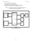
* In the V.35 option, check that main and sub-channel’s three switches are set to the same
position.
OPERATION RSD-20 OPERATOR'S MANUAL
3.3