


Connections & Setup
Chapter 1 9
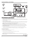
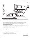
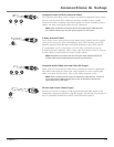
How to Connect: TV + Satellite Receiver + VCR
1. Connect your cable or off-air signal to ANTENNA A.
If you have cable and off-air antennas, connect the cable signal to ANTENNA A INPUT (antenna A is the only source for
GUIDE Plus+ System). Connect the off-air antenna to ANTENNA B INPUT. If you have only an off-air antenna, connect it
to ANTENNA A INPUT.
2. Connect your VCR to your TV.
A. Connect the VCR’s audio/video outputs to INPUT 1 (audio/video) on the TV using composite audio/video cables.
B. Connect the VCR’s audio/video inputs to RECORD OUTPUT on the TV. This enables recording of digital programs
(unless copy protected, using DVI HDTV or component video formats), as well as analog programs.
3. Connect your Satellite Receiver to your TV.
Connect the satellite receiver’s audio/video output jacks to the INPUT 2 AUDIO (R and L) and VIDEO jacks on the TV
using composite cables. If your satellite receiver has an S-Video output, you can make the video connection by using the
S-Video jacks instead. If your satellite receiver has component outputs, then use INPUT 3 or 4.
Note: If you are using an S-Video cable or component video cables, you must also use audio cables. The S-Video cable
and component video cables only transfers video information.
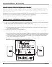
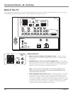
Viewing the Components
1. Turn on the TV and the component(s) you want to view.
2. Press the TV button on the remote control.
3. Press the INPUT button on the remote control to scroll through the video inputs.
• The VCR can be viewed on the INPUT 1 channel.
• The satellite receiver can be viewed on the INPUT 2 channel.
Note: You can set up the TV to automatically tune to the correct input channel. This is called Auto Tuning. (See Chapter 3
for more information.)
Go to page 17
Satellite
Receiver
VCR
TV
VIDEO
AUDIO
L
R
S-VIDEO
SATELLITE
RECEIVER
CABLE
OFF-AIR ANTENNA
VIDEO
INPUT 1
AUDIO
INPUT 1
L/
MONO
R
VIDEO
INPUT 2
AUDIO
INPUT 2
S-VIDEOS-VIDEO
VIDEO
INPUT 3
AUDIO
INPUT 3
V
L/
MONO
R
V
L/
MONO
R
V
P
B
Y
P
R
L/
MONO
R
VIDEO
INPUT 4
AUDIO
INPUT 4
AUDIO
INPUT 5
L/
MONO
R
V
P
B
Y
P
R
VIDEO
INPUT 5
R
L
LEFT
EXT
SPEAKER
SELECT
INTERNAL
SPEAKER
SOURCE
EXTERNAL AMPLiFIER
MAXIMUMPOWER RATING!
(60 WATTS into 8 OHMS)
CENTER CHANNEL INPUT
RIGHT FIXED/VARIABLE
AUDIO
OUTPUT
EXTERNAL SPEAKERS
TV EXT AMP
INT W/
EXT
SURR
ANTENNA B
INPUT
ANTENNA A
INPUT
ETHERNET
G-LINK
VIDEO
RECORD
OUTPUT
AUDIO
R
L
DIGITAL
AUDIO
OUTPUT
TV
ANTENNA IN
VIDEO
AUDIO
L
R
ANTENNA OUT
IN
OUT
VCR
VIDEO
AUDIO
L
R
OR
DVI-HDTV
Connect G-LINK Cable (see page 17)
1
2B
3
2A