


Connections & Setup
14 Chapter 1
VIDEO
INPUT 1
AUDIO
INPUT 1
L/
MONO
R
VIDEO
INPUT 2
AUDIO
INPUT 2
S-VIDEOS-VIDEO
VIDEO
INPUT 3
AUDIO
INPUT 3
V
L/
MONO
R
V
L/
MONO
R
V
P
B
Y
P
R
L/
MONO
R
VIDEO
INPUT 4
AUDIO
INPUT 4
AUDIO
INPUT 5
L/
MONO
R
V
P
B
Y
P
R
VIDEO
INPUT 5
R
L
LEFT
EXT
SPEAKER
SELECT
INTERNAL
SPEAKER
SOURCE
EXTERNAL AMPLIFIER
MAXIMUM POWER RATING
(60 WATTS into 8 OHMS)
CENTER CHANNEL INPUT
RIGHT FIXED/VARIABLE
AUDIO
OUTPUT
EXTERNAL SPEAKERS
TV EXT AMP
INT W/
EXT
SURR
ANTENNA B
INPUT
ANTENNA A
INPUT
ETHERNET
G-LINK
VIDEO
RECORD
OUTPUT
AUDIO
R
L
DIGITAL
AUDIO
OUTPUT
TV
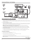
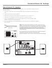
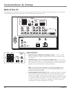
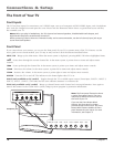
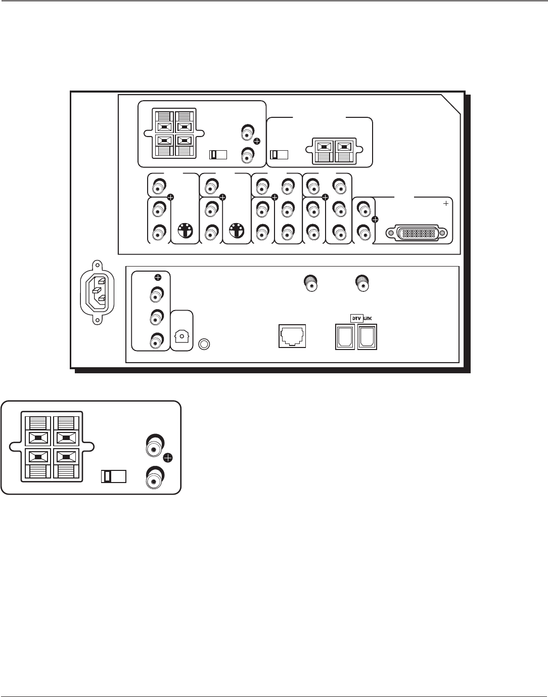
Back of the TV
The diagrams below illustrate each of the back panel jacks found on the TV. When connecting cables, be sure to connect
corresponding outputs and inputs (video to video, right audio to right audio, etc.).
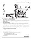
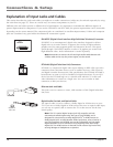
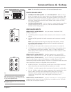
AUDIO OUTPUTS
• RIGHT and LEFT EXTERNAL SPEAKER Terminals Used to connect
external speakers for improved right and left sound, or surround sound.
See page 10.
• SPEAKER SELECT - EXT. or INT W/EXT SURR Switch Lets you direct
where the output of the TV’s internal speakers goes. With the switch in the
EXT position, you hear the TV’s external speakers. In INT W/EXT SURR
position, you hear the internal and external speakers
.
Note: To turn the TV’s internal speakers on and off, press MENU on the
remote control and choose Audio. Then choose Fixed/Variable Out from
the menu and choose an option.
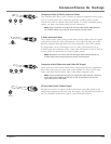
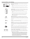
• FIXED/VARIABLE AUDIO OUTPUT L/R Provides fixed-level or variable-
level audio output from the television. Fixed (Fixed/Variable is a menu
setting) audio output is ideal for audio recording or for connecting to an
A/V receiver amplifier (an auxiliary baseband component) when you want
to control the volume through the A/V receiver instead of the TV. Variable
is used to connect an A/V receiver or amplifier (an auxiliary baseband
component) for variably-controlled stereo output.
R
L
LEFT
EXT
SPEAKER
SELECT
RIGHT FIXED/VARIABLE
AUDIO
OUTPUT
EXTERNAL SPEAKERS
INT W/
EXT
SURR