


7
(1)
(2)
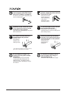
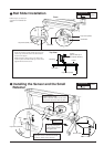
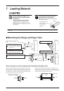
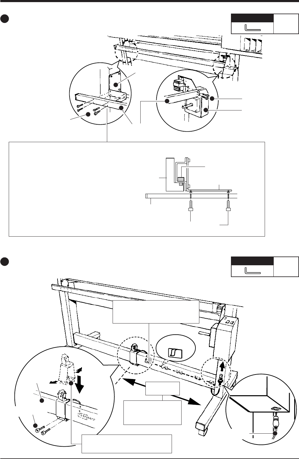
Rail Slider Installation
Follow steps (1) and (2) in
sequence to install the rail
slider.
Required tool
Small
Front
Required tool
Small
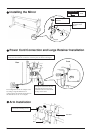
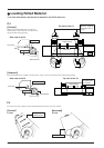
Installing the Sensor and the Small
Retainer
If the screw holes for the small cap screws do
not line up, loosen all screws at the locations
shown in the figure.
While loosened, line up the screw holes and
secure in place with the small cap screws, then
tighten the loosened screws.
Cap screw (small)
Rail slider
Frame
Loosen
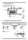
(Screws lined up in
the vertical direction)
Stand leg
Top View
Rail slider
Frame
Cap screw (small)
Cap screw (small)
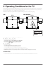
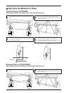
Control box
Cap screw (medium)
Sensor cable
680 mm
±20 mm
(26-3/4 in.
±3/4 in.
)
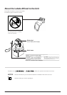
Align by placing the
gauge packed with the
TU against this.
Cable retainer (small)
Affix to the rear surface of the stand
and secure the sensor cable in place.
Open the sensor to the front and back
as shown, and fit it onto the stay.
Stay
Orientation of the
retainer (small)