


12
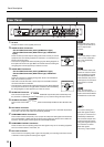
Panel Descriptions
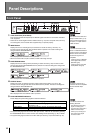
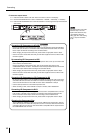
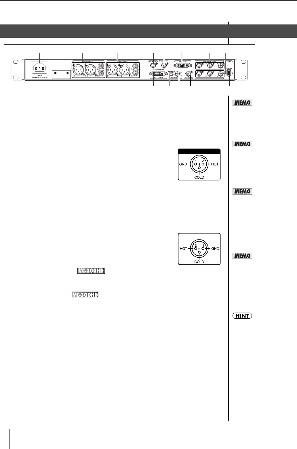
1 AC Inlet
Accepts connection of the supplied power cord.
2 AUDIO OUTPUT Connectors
CH1 and CH2 Connectors (XLR Type/Balanced Type)
CH3 and CH4 Connectors (RCA Phono Type, Unbalanced
Input)
These connectors provide output of analog audio. Here is where you connect
equipment such as monitoring speakers or a television, or a video deck if you
intend to record the output.
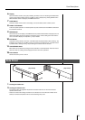
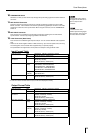
* This device is equipped with balanced (XLR) type jacks. Wiring diagrams for
these jacks are shown to the right. Make connections after first checking the
wiring diagrams of other equipment you intend to connect.
3 AUDIO INPUT Connectors
CH1 and CH2 Connectors (XLR Type/Balanced Type)
CH3 and CH4 Connectors (RCA Phono Type, Unbalanced
Input)
These are connectors for inputting analog audio. Audio to be embedded in
HDV, DV, and SDI is input here.
* Audio that is included with HDV or DV is output from the AUDIO OUTPUT
connectors CH1/CH2 or CH3/CH4.
* This instrument is equipped with balanced (XLR) type jacks. Wiring diagrams
for these jacks are shown to the right. Make connections after first checking
the wiring diagrams of other equipment you intend to connect.
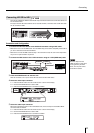
4 HD-SDI OUT Connector
This connector outputs SDI. Switching of HD-SDI/SD-SDI output takes place automatically when
the procedure in "Selecting the video output format" (p. 27) is used to change the output format.
5 HD-SDI IN Connector
This connector receives SDI input. The input SDI is automatically identified as either HD-SDI or SD-
SDI.
6 DVI-I INPUT Connector
This connector receives DVI-I signal input. Video that is output from a PC or other DVI output device
is input here. The input video format is automatically identified.
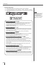
7 COMPONENT INPUT Connectors
This connector receives component (Y, Pb, Pr) input. HD component video signals from HD devices
such as the EDIROL V-440HD and SD component video signals from devices such as DVDs are
input here. The HD signals and SD signals are automatically identified.
8 COMPONENT OUTPUT Connectors
These connectors are for outputting component video signals. They are for connecting equipment
such as a monitor television, video mixer, etc.
9 DVI-I OUT Connector
This connector is for outputting a DVI-I signal. This is typically for connecting a flat-screen monitor
or television monitor capable of receiving DVI-I signals.
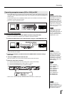
Rear Panel
1 64 5
109 11 12 13
2 73 8
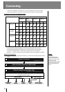
AUDIO OUTPUT CH1, CH2
See the tables to the right for
the signal formats that can be
input or output to each
connector.
AUDIO INPUT CH1, CH2
You can apply delay to output
audio. For more information,
refer to 240: "AudioDelay
Time" (p. 34).
See p. 13 for the signal
formats that can be input to, or
output from the HD-SDI INPUT
and HD-SDI OUT connectors.
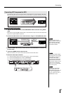
DVI-I
DVI-I receives analog and
digital video signals. VGA (D-
sub 15-pin) is connected via a
commercially available DVI-
VGA conversion adapter. This
manual uses DVI-A to denote
analog video signals input from
DVI-I and DVI-D to denote
digital video signals.
* See "DVI" (p. 38) for details.
When connection cables with
resistors are used, the volume
level of equipment connected
to the inputs (AUDIO INPUT,
AUDIO OUTPUT) may be low.
If this happens, use connection
cables that do not contain
resistors.
926a
922