


10 Model IIC-200 Operation Manual Version 1.A
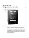
Hardware Overview
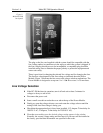
The IIC-200 consists of a printed circuit board and a modular high voltage supply which
are mounted in a stand-alone chassis.
The IIC-200 contains circuitry for the following functions:
A variable high voltage power supply for the MCP voltage. The MCP voltage is a
linear function of the voltage supplied by the MCP Gain potentiometer.
Upper and lower limit circuits for the MCP voltage (normally set to -500 V and
-800 V respectively for Gen II).
Note:
When the image intensifier and IIC-200 are purchased from Roper Scientific
as part of the same order, the upper limit circuit will be set for the maximum limit of
the intensifier. The upper limit circuit also provides a slow turn-on during power-up.
High-voltage adjustment circuit for the voltage between MCP-Out and the Phosphor
(normally set for -5500 V for Gen II Intensifiers).
Alarm and shutdown circuit to shut down the high voltage and bring the MCP
voltage to almost zero if an over-current condition exists due to excessive light on
the Photocathode. This circuit additionally actuates an audible alarm if an over-
current condition occurs. The circuit automatically resets and retries after about 0.5
seconds. Thus it will not prevent intensifier damage if excessive light is allowed to
continuously fall on the intensifier.
Automatic Brightness Control circuit to reduce the MCP voltage in response to
increasing light intensity on the Photocathode. This can be useful in focusing. When
properly interfaced to a Princeton Instruments CCD Controller, the Brightness
Control circuit uses a sample/hold to sample the phosphor current during CCD
exposure and hold it between exposures. The sample/hold is inactive in the Gate
mode. The automatic Brightness Control function should be turned off for normal
operation, since the response isn’t linear (and may not even be constant) when it is
used.
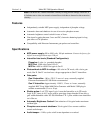
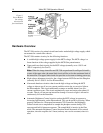
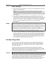
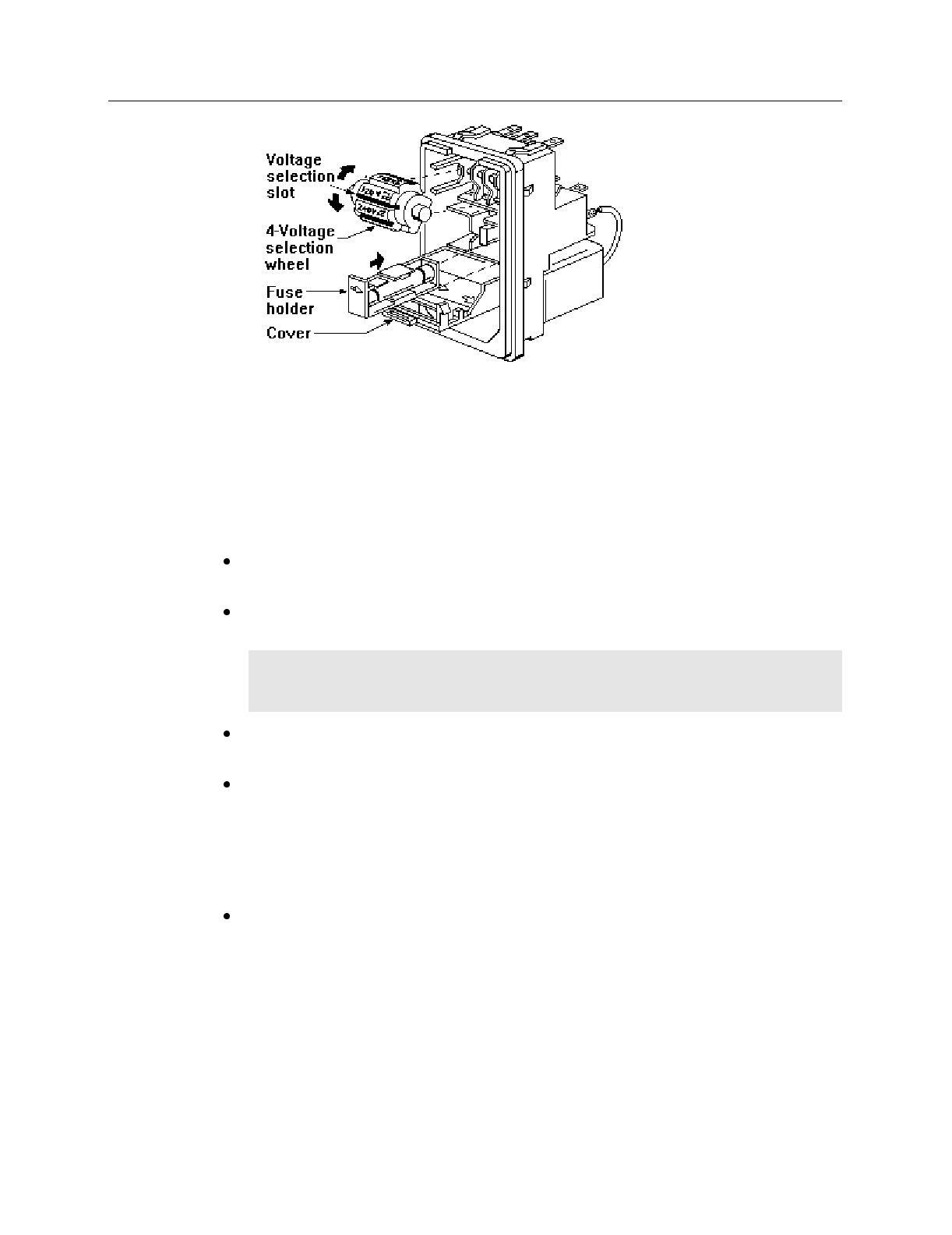
Figure 3.
Power Module
line voltage
selection and
fuse installation