8 Model IIC-200 Operation Manual Version 1.A
Front Panel Features
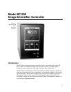
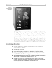
MCP GAIN:
This adjustment is used to control the gain of the MCP by controlling the
voltage across it. Display units are arbitrary.
SHUTTER/GATE:
This switch selects between Gate mode or Shutter mode. In Gate
mode, the intensifier is normally off and a high-voltage gate pulse is needed to
turn it on. In the Shutter mode, the intensifier is normally on, and a TTL logic
low (0 V) must be applied to the back panel Shutter In BNC connector to turn
the intensifier off. The Shutter Monitor output provided by Princeton
Instruments CCD Controllers can be applied to turn off the intensifier during
readout.
AUTO BRIGHT CONTROL ON/OFF:
This switch turns the automatic brightness
control feature on or off. Brightness control reduces the MCP gain when
exposed to high light levels. This compresses the output dynamic range to keep
signal levels on screen during set-up.
Note:
When making quantitative measurements,
AUTO BRIGHT
should be
OFF
.
MCP POWER ON/OFF:
This switch turns the intensifier voltages on or off while
chassis power remains on.
POWER ON/OFF:
This switch turns the IIC-200 chassis power on or off.
Back Panel Features
GATE IN:
This is the input for high voltage (-200 V) gate pulses used to turn on the
intensifier. In units intended for use with a Gen II intensifier,
GATE IN
is a
BNC connector. In units supplied for operation with a Gen IV Intensifier, which
requires a gate pulse of approximately -1000 V,
GATE IN
is a type SHV
connector. A high-voltage pulser is required in both cases.
SHUTTER IN BNC:
This TTL (5 V) input is used to synchronize the intensifier with
the CCD exposure time or to hold the intensifier on in Shutter mode operation.
If the front-panel Shutter/Gate switch is set to
SHUTTER
, the intensifier will be biased
on if the Shutter In connector is floating, or if +5 V is applied. As a result, the intensifier
is particularly vulnerable to overload damage in this mode. If the switch is set to
GATE
,
the Shutter In connector is inactive and the intensifier can only be biased on for the
duration of high-voltage gate pulses applied to the Gate In connector.
INTENSIFIER H.V.P.S:
This connector is used to supply High Voltage DC power to
the intensifier through the cable supplied by Roper Scientific. The high voltage
cable must always be connected
at both ends
before turning the power on.
POWER MODULE:
This module contains the line-cord socket, line fuse and line
voltage selection assembly. The power and fuse requirements are printed on the
panel above the power module.
WARNING


