


6 Model IIC-200 Operation Manual Version 1.A
The IIC-200 allows both Shutter and Gated modes of operation. Gating pulses can range
from 5 nsec to DC. Longer gate experiments can also use the 5 volt logic electronic
shutter control.
Dangers and Warnings
Voltages inside the IIC-200 may exceed 10,000 volts. To avoid possible hazard to
personnel, use the instrument only with the proper connectors and cables and only for the
purposes for which it is designed, i.e. the operation of image intensifier tubes which are
contained in proper housings and equipped with compatible connectors. Adequate
precautions must be taken to prevent persons from making contact with the output of the
IIC-200.
Never plug the AC cord into an outlet which is not properly grounded. Never attempt to
operate the unit without its covers in place.
Never operate the unit with the high voltage cable disconnected. The high voltage
connectors are designed to seal out air to avoid arcing. An open high voltage connector
is a danger to personnel and can cause damage to the equipment. Connections should be
made before power is turned on.
Before disconnecting any cables, turn the power off and wait at least 5 minutes for
voltages to decay to safe levels.
The IIC-200 chassis uses a three wire power cord for connection to the power source and
to a protective ground. The exposed parts of the instrument, including the BNC shields,
are connected to the outlet ground to protect against electrical shock. Always use an
outlet which has a properly connected protective ground. Never make connections to
other instruments which might have voltages on BNC shields. Disconnecting the
protective earth terminal, inside or outside the chassis, or tampering with its operation
may render the IIC-200 dangerous and is prohibited.
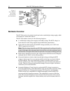
The high-voltage Gate In connector (BNC with Gen II intensifier, SHV with Gen IV
intensifier) is located next to the Shutter In BNC connector on the back panel. The
Shutter In BNC connector is the input for a TTL (5 V) logic level signal and should
never be connected to a high-voltage gate pulse or damage could occur. Always take
care not to confuse these inputs.
During manufacture, a Model IIC-200 is configured for operation with a Gen II
Intensifier or with a Gen IV Intensifier,
but not for operation with both types
. The two
types are
not
interchangeable. Units configured for operation with a Gen IV Intensifier
will ordinarily have a green identification label on the back panel. Units configured for
operation with a Gen II Intensifier will have a blue label. Your detector may have
corresponding color-coded labeling. Check with the factory if you are in doubt. Using the
wrong IIC-200 type with your intensifier could damage the intensifier. Damage due to
such misuse is
not
covered by the Warranty.
DANGERS
WARNINGS