


System Overview
Q-1500d Series Installation/Operation Manual 13
PRE
L
IMINAR
Y
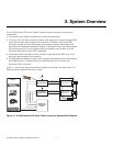
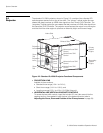
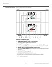
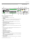
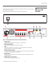
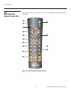
Rear Panel LayoutFigure 2-5 shows the rear connector panel on the Primary DHD Controller.
Figure 2-5. Primary DHD Controller Rear Panel
1. MAIN POWER SWITCH
Disconnects or applies power to the DHD Controller.
2. TRIGGERS
Connection for up to three (3), 12-volt trigger-controlled devices such as retractable
screens or screen masks. Output current is limited to 250 milliamperes (mA).
3. USB
A standard, USB Series “B” connection to a personal computer, for performing
software upgrades and other service procedures.
4. RS-232 (To Accessory Box)
A male, 9-pin D-sub connector for interfacing with the Secondary DHD Controller.
(Use a “null-modem” serial cable for this connection.)
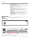
5. Display Control
Connect this to the RS-232 input on the primary (top) optical engine on the Q-1500d
projector.
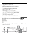
6. IR
Wired input from a Niles- or Xantech-compatible, infrared (IR) repeater system. It is a
3.5-mm, mini phono jack, wired as follows:
Ring = No connection
Tip = IR Input
Sleeve = Ground
7. POWER INPUT (100 to 240 VAC)
Connect the DHD Controller to power here.
8. HD2 Input (5 x Analog BNCs)
Connect the HD 2 input to the Primary Analog output on the Brightness Acceleration
Engine.
The HD 1 input is not used with the Q-1500d. Connect your Component/RGBHV
sources to the Brightness Acceleration Engine.
9. Video 1 Input (RCA)
Connect the Video 1 input to the Primary Composite video output on the Brightness
Acceleration Engine.
ABCDE
H
DHD4
Primary
Do not connect any video source directly to this box.
Pr
R
Y
G
Pb
B
Pr
R
HV
HD2
T
Video
Video 3PrPb
HDMI 1
HDMI 3
FG
HDMI Out
Audio Only
HDMI Out
To Display
Ethernet
PC / Control
RS232
TRIGGERS
USB RS-232
123
Display Control
IR
P
r
R
P
rP
b
V
i
de
o3
G
B
R
12
8
7
6
2
543
11
1413
1
9 10