


APP-1
APPENDIX 1
TXD
RXD
GND
CTS
DSR
PC
TXD
RXD
GND
+9V
+9V
Projector
3
2
5
8
6
3
2
5
8
6
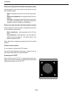
Recommended
Method
Pin to Pin
All 9 Pins
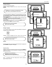
RS 232 Control
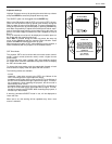
By far, the most accurate way to control or integrate the DTV-992 / 992 ULTRA into a home theater system is by RS
232 control. In this section, you will find hardware configuration and how to format the control data, command strings
and examples.
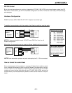
Hardware Configuration
RS232 Connector 9PIN D-SUB PC-AT TYPE. Projector has female type.
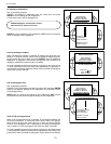
T
o establish communications with the projector
, the following conditions must be made:
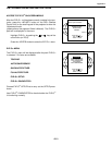
PIN OUTS FOR 9 PIN
1: CD Carrier Detect
2: RXD Receive Data
3: TXD Transmit Data
4: DTR Data Term Ready
5: GND Signal Ground
6: DSR Data Set Ready
7: RTS Request To Send
8: CTS Clear To Send
9: Ring Indicator
The Protocol Necessary
For Communications:
8 Data Bits, No Parity, 1 Stop Bit
Baud Rate is selectable between 8
rates at the projector up to 9600
Baud (9600 is default).
TXD
RXD
GND
CTS
DSR
PC
TXD
RXD
GND
+9V
+9V
Projector
3
2
5
8
6
3
2
5
4
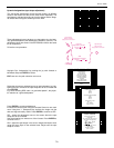
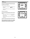
No Flow Control
Jump Pins
4,6,8 at PC
side
DTR
Tied together
at computer
NOTE: All wires are straight through. DO NOT cross PINS 2 to 3 as in a null
modem configuration.
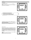
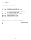
Alternatively
, the connections can be made as follows (absolute minimum of wires):
NOTE: Some automation systems may only use/require pins 3, 2, 5 be connected.
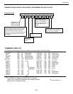
How to format the control data
Every command sent to the projector is a group of 9 bytes that is called a record.
Even a simple ON command is sent as a record. Below is an explanation of the syn-
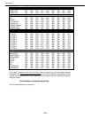
tax of a record. It is not necessary to memorize the syntax since the next section
contains a chart of strings that work with any DTV-992 / 992 ULTRA and can be
entered directly into most automation systems to control all the functions of the pro-
jector.