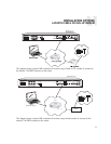
In a CAV6.6 system, the SMS3’s three streams
are configured as three sources. Its composite
video signal is shared between all three sources
by using an RCA cable to loop the video from
source out to source in.
1. Connect the three RCA cables from the SMS3
three sources to the controller amplifier source
inputs. For RNET-enabled systems, SMS3 source
numbers are preconfigured:
SMS3 Stream 1=RNET Source 3
SMS3 Stream 2=RNET Source 4
SMS3 Stream 3=RNET Source 5
These source numbers can be re-configured from
the SMS3 if necessary.
2. Connect a CAT-5 patch cable from the CAV6.6
RNET Link Out port to the SMS3 RNET Link In port.
3. Using a straight-through Ethernet RJ-45 CAT-5
patch cable, connect from the SMS3 LAN port to
an open port on the network router.
4. Connect the composite video cable from the
SMS3 composite video port to the Source 3
video input.
5. Use an RCA loop cable to connect the
Source 3 video out to Source 4 video in. Loop
another cable from Source 4 video out to
Source 5 video in.
6. Connect an RCA cable from the video source’s
video in jack to the CAV6.6’s Zone Video Output.
The SMS3 media server uses a video display to
show the graphical user interface during opera-
tion. The SMS3 outputs one video signal that is
available in three formats - composite video,
S-video and VGA.
To view the SMS3 interface, connect a video dis-
play (TV, display panel, etc.) directly to the SMS3
back panel using an S-video, composite video or
VGA connection. Another viewing option is con-
necting a computer monitor to the SMS3 15-pin
VGA connection on the rear panel. (The VGA
output cannot be used when either the S-
video or composite video outputs are in use.)
There are several options available to distribute
the SMS3 video display.
With video distribution systems such as the
CAV6.6, the composite video signal must be
shared between all three streams (sources). The
CAV6.6 has a video signal output for each
source input that can be looped to the next input
with an RCA video patch cable.
For non-video distribution systems such as the
CAi or A-BUS, an RF modulator and RF distribu-
tion amplifier may be used as an alternate means
of distributing video to each room in the system.
With one video stream out, if there is more than
one video interface (TV, display) using the same
signal, all show the same view and all will update
at the same time. When a menu command is
received by the SMS3, the video signal will dis-
play the stream that was the target of the com-
mand.
Note: The video display is auto-sensing; it is
looking for a load on the composite or S-video
connection. If the video is connected after the
SMS3 is powered, there will be no signal, as the
SMS3 default setting is VGA output only. Simply
reboot the SMS3 after connecting to a TV or
video display, and the video display will sense the
load.
INSTALLATION OPTIONS
VIDEO DISPLAY
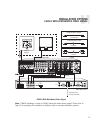
CAV6.6 With Distributed Video Signal
12


