


English-58
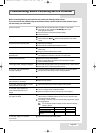
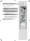
Pin Configurations
Pin Description
1 Rx 2-
2 Rx 2+
3 Grounding
4 No connection
5 No connection
6 DDC Clock (SCL)
7 DDC Data (SDA)
8 Analog Vertical Sync
9 Rx 1-
10 Rx 1+
11 Grounding
12 No connection
13 No connection
14 DDC Input Power (+5V)
15 Self-Raster
Pin Description
16 Output Signal Connection
17 Rx 0-
18 Rx 0+
19 Grounding
20 No connection
21 No connection
22 Grounding
23 Rx C-
24 Rx C+
DVI - D Connector
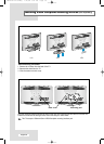
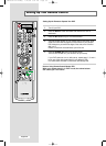
Pin Separate H/V Composite H/V
1 Red (R) Red (R)
2 Green (G) Green (G)
3 Blue (B) Blue (B)
4 Grounding Grounding
5 (DDC return) Grounding (DDC return)
6 Grounding - Red (R) Grounding - Red (R)
7 Grounding - Green (G) Grounding - Green (G)
8 Grounding - Blue (B) Grounding - Blue (B)
9 No connection No connection
10 Grounding - Sync. / Self test Grounding - Sync. / Self test
11 Grounding Grounding
12 DDC - SDA (Data) DDC - SDA (Data)
13 Horizontal Sync. Horizontal/Vertical Sync.
14 Vertical Sync. Not used
15 DDC - SCL (Clock) DDC - SCL (Clock)
D - Sub Connector
BN68-00751C-00Eng 7/20/04 5:21 PM Page 58