


14_ connecting with other device
connecting with other device
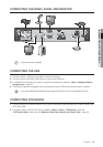
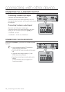
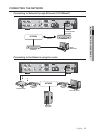
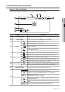
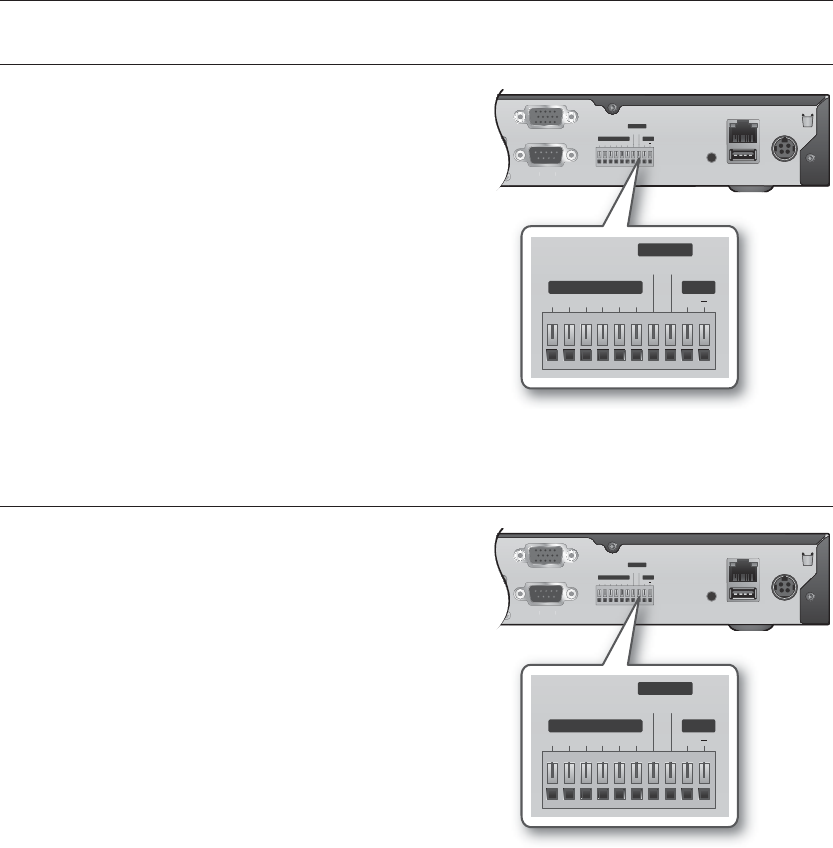
CONNECTING THE ALARM INPUT/OUTPUT
Connecting the alarm input signal
Connection port for the alarm input signal.
Connect one strand of the sensor signal line to one of 4
strands of the alarm input port, and connect the other strand
to the [G] port.
Connecting the alarm output signal
Connection port for the alarm output signal.
Connect one strand of the sensor signal line to the alarm
output port and connect the other to the [COM] port.
• ALARM IN : 5mA sink
• ALARM OUT : 24V DC 1A, 125VAC/0.5A
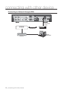
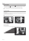
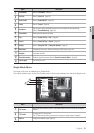
CONNECTING THE RS-485 DEVICE
Connect the rear [RS-485 +, –] port to the PTZ camera or system
keyboard.
M
You can connect and control the PTZ camera which
supports the RS485 communication.
Check if the RS-485 device is compatible with the product
first.
Pay attention not to change the polarity (+/-) of the
RS-485 device when connecting it.
Depending on camera’s type, connection polarity can be
different.
For further information, refer to the respective PTZ
Camera’s documentation.
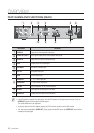
1234 GG +
1COM
ALARM IN
NETWORK
USB
CONSOLE
VGA
SERIAL
IN
OUT
DC 12 V
RS-485
ALARM OUT
US
B
CO
N
SO
LE
S
ERIAL
1234 GG +
1 COM
ALARM IN
RS-485
ALARM OUT
1234 GG +
1COM
ALARM IN
NETWORK
USB
CONSOLE
VGA
SERIAL
IN
OUT
DC 12 V
RS-485
ALARM OUT
US
B
CO
N
SO
LE
S
ERIAL
1234 GG +
1 COM
ALARM IN
RS-485
ALARM OUT