


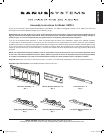
ENGLISH
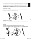
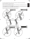
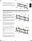
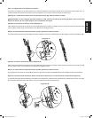
Step 6: Add Safety Bolts (Tilting Monitor Brackets only)
Thread a Safety Bolt (I) into the bottom portion of each Tilting Monitor Bracket (D & E) approximately 1/4″ as shown in Diagram 6.
NOTE: Do not tighten the Safety bolt (I). The Safety Bolt is tightened after the television and Tilting Monitor Brackets (D & E) are
attached to the Wall Plate Assembly (A).
Step 7: Congure Wall Plate Assembly
The Wall Plate Assembly (A) can be adjusted in width from 27″ to 42″ [686 mm to 1067 mm]. Determine how wide you want the Wall
Plate Assembly based on the following criteria:
• Width of television (Wall Plate Assembly should be congured so the total width is less than the overall width of your television)
• Width of Hole Pattern on television (Wall Plate Assembly should be wider than the horizontal distance between threaded inserts on the
back of your TV by at least 2″ [50.8 mm])
• Stud Spacing (Sanus recommends attaching Wall Plate Assembly to three studs for televisions over 125 lbs. [56.7 Kg])
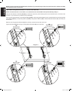
To adjust the width of the Wall Plate Assembly (A):
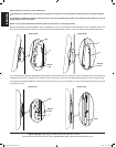
Diagram 6
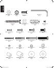
I
D & E
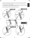
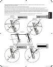
Remove the Center Plate of the Wall Plate Assembly (A) as
shown in Diagram 7B.
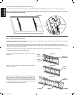
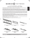
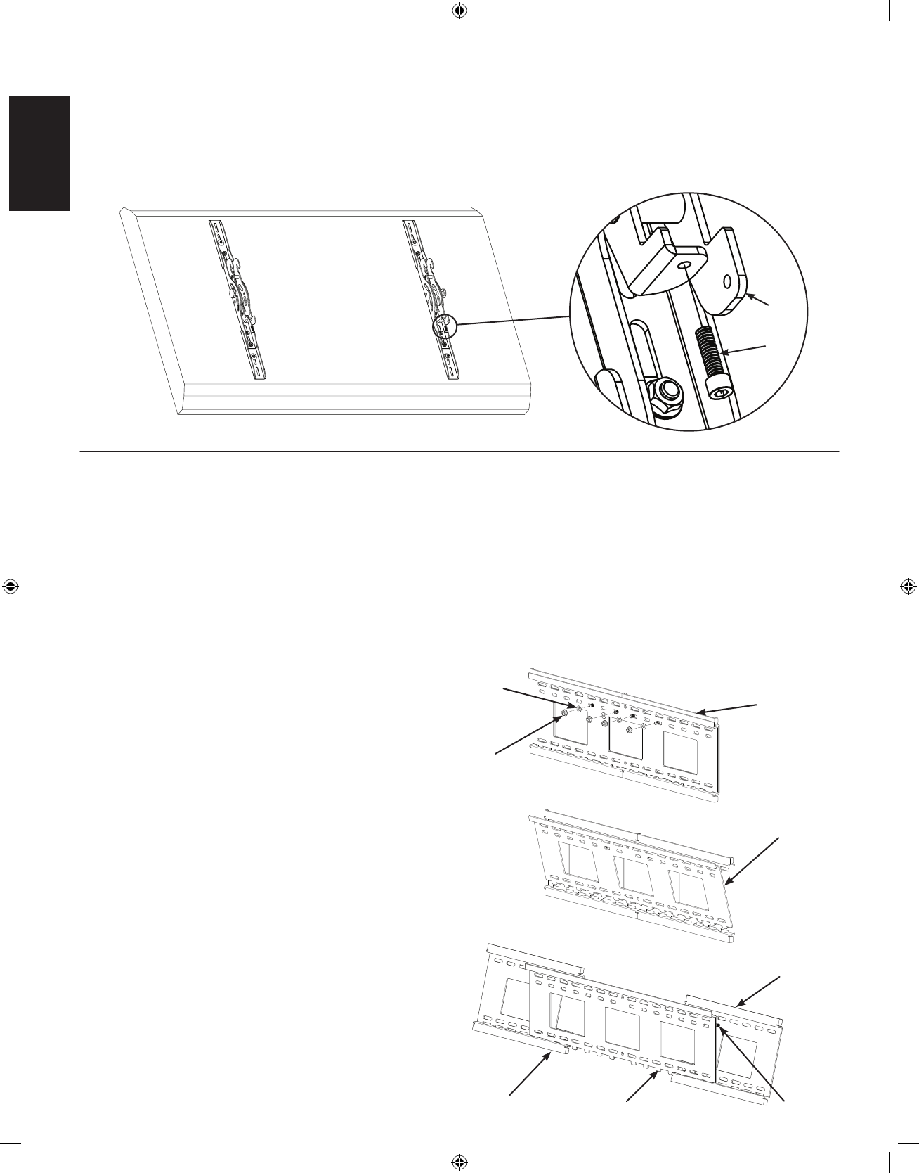
Seperate the Left and Right Extension of the Wall Plate Assembly
(A) and set them to so that their outer edges are equal to the
desired width; then, insert the Center Plate so the teeth on its
bottom t into the slots in the Left and Right Extension, making
sure that the Threaded Studs t through the center row on holes
in the Center Plate as shown in Diagram 7C.
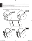
Diagram 7A
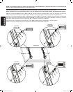
Flange
Nut
Wall Plate
Assembly (A)
Nylon
Washer
Diagram 7B
Center
Plate
Diagram 7C
Left
Extension
Center
Plate
Right
Extension
Threaded
Studs
Remove each Flange Nut and Nylon Washer as shown in
Diagram 7A
VMPL3_051106_ML.indd 10 7/17/06 11:37:14 AM