


ENGLISH
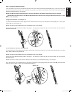
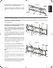
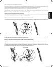
Wall Plate
Assembly (A)
Center
Plate
Right
Extension
Threaded
Studs
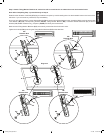
CAUTION: All four Threaded Studs must pass through
the Center Plate for the installation to be safe.
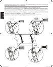
Using the previously removed Flange Nuts and Nylon
Washers, secure the Right and Left Extension to the Center
Plate as shown in Diagram 7D, and securly tighten the Flange
Nuts.
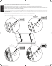
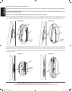
Step 8: Mount the Wall Plate Assembly; Wood Stud, Brick, Solid Concrete, and Concrete Block mounting options are provided.
CAUTION: On all installations, two Lag Bolts (K) must pass through each Wall Plate Extension. Only the fth and sixth Lag
Bolts may pass through the Center Plate (A).
Diagram 7D
Flange
Nut
Nylon
Washer
Left
Extension
Center
Plate
Right
Extension
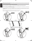
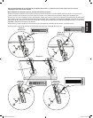
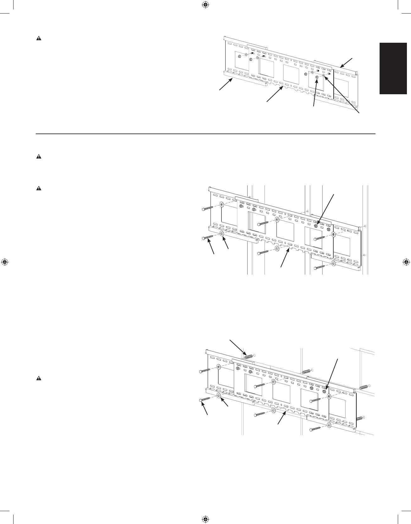
Wood Stud Mounting:
CAUTION: Do not overtighten the Lag Bolts (K). Tighten
the Lag Bolts only until the lag Bolt Washer (L) is pulled
rmly against the Wall Plate Assembly (A).
NOTE: The Wall Plate Assembly (A) must be mounted
on two or three studs at least 12″ [304.8 mm] apart,
and three studs are recommended for televisions over
125 lbs [56.7 Kg].
Use a high quality stud sensor to locate two or three adjacent
studs; then, using the Wall Plate Assembly (A), as a template,
mark a location at each of the studs using the top row of slots
on the Wall Plate Assembly and the corresponding slot in the
bottom row.
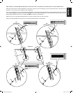
Pre-drill a 2.5″ [63.5 mm] deep into the studs, using a 3/16″
drill bit. Place the Wall Plate Assembly (A) with its at surface
against the wall and the Flange Nuts toward the top; then
secure the Wall Plate Assembly using the Lag Bolts (K) and
Lag Bolt Washers (L) as shown in Diagram 8A.
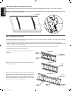
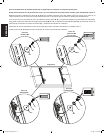
Brick, Solid Concrete, and Concrete Block Mounting:
Use the Wall Plate Assembly (A) as a template to mark six
locations on the wall. Three in the top row of slots and three
more directly below in the bottom row of slots.
CAUTION: Never drill into the mortar between the
blocks.
Carefully pre-drill six 2.5″ [63.5 mm] deep holes with a 1/2″
masonry bit.
Insert a Concrete Anchor (M) into each pre-drilled hole so it
is ush with the concrete, brick, or concrete block surface,
even if there is a layer of drywall or other material in front of
the surface.
Place the Wall Plate Assembly (A) with its at surface against
the wall and the Flange Nuts toward the top; then, attach the
Wall Plate Assembly to the wall using the six Lag Bolts (K)
and Lag Bolt Washers (L) as shown in Diagram 8B.
Diagram 8A
A
K
L
Flange
Nut
Diagram 8B
Flange
Nut
M
K
L
A
VMPL3_051106_ML.indd 11 7/17/06 11:37:17 AM