


— 13 —
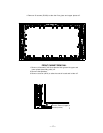
The CPU (IC801) is programmed so the set will go to the standby mode when there is a circuit failure as described below.
(Refer to”Power Supply Lines” page 38.)
1. Power Failure 1: Detected voltage failure for analog circuit. (Connected to IC801 pin 52.)
(Normal: High, Failure: Low)
2. Power Failure 2: Detected voltage failure for Audio AMP IC. (Connected to IC801 pin 53.)
(Normal: Low; Failure: High)
3. Power Failure 3: Detected voltage failure for digital circuit. (Connected to IC801 pin 54.)
(Normal: High, Failure: Low)
4. Temperature Failure: Detected temperature failure for Main Power Unit. (Connected to IC801 pin 57.)
(Normal: Low, Failure: High)
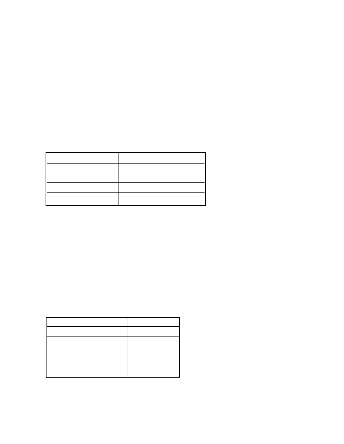
LED Flashing
When IC801 detects the Power Failure the LED will flash to indicate a power failure has occurred.
The number of flashes will be determined by the type of failure detected as shown below.
POWER FAILURE CIRCUIT
Note: If power failure is detected 3 times in 15 minutes, the set will enter the standby mode and cannot be
switched On. To reset the operating programs of the CPU it is necessary to disconnect the AC cord
for a short time.
History of Power Failure
When finishing the repair or stopping the Power Failure, the history of past failures can be checked.
To see the history
1. Enter the service mode. See “Service Adjustments” page 3.
2. Select Item No. 355 POWER ERROR from the Service Adjustment Data Table.
History of Power Failures (Item No. 355)
Note: If simultaneous failures have been detected, the sum of each data is displayed.
For example:
Power failures 1 & 2
01h + 10h = 11h(17)
Attention:
After finishing service, reset the data of Item No. 355 with the < or > keys to “00h(0).”
Times of Flashes Failure Name
1 Power Failure 1
2 Power Failure 3
3 Power Failure 2
4 Temperature Failure
Failure Name Data
No Failure 00h(0)
Power Failure 1 01h(1)
Power Failure 3 04h(4)
Power Failure 2 10h(16)
Temperature Failure 20h(32)