


4
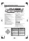
Names of each part and connections
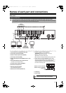
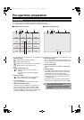
Rear panel
1 Video input terminal (VIDEO IN/LOOP OUT)
2 Video output terminal (S-VIDEO)
3 Monitor 2 video output terminal (MON2)
4 Video output terminal (MAIN)
5 Audio input/output terminal (AUDIO IN: CH1 - CH4/
OUT1)
6 VGA (Video Graphics Array) output terminal
Connects to the PC VGA monitor.
7 External sensor terminal (ALARM IN)
8 Network terminal (LAN: P5)
9 RS-232C terminal (RS-232C)
For maintenance purposes.
F RS-485 control terminal (RS-485: P6)
G System changeover switch (SWITCH)
TERMINATE: RS-485 termination switch (P11)
RSV: For maintenance purposes.
VGA: Monitor selection switch (P9)
PAL: Television mode (PAL/NTSC) switching switch (P9)
H Alarm output terminal (ALARM OUT: CH1 - CH4)
When the configured alarm output conditions are met, a
relay signal is output to one or more external alarm
devices connected to the alarm output terminals. These
terminals are normally open.
I Cooling fan
J Power socket
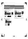
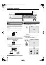
Basic connections
• Do not turn this unit on before all the connections are complete. Read the instruction manual of each unit carefully.
• Make sure each unit is connected properly as faulty connection may result in the unit emitting smoke and/or being damaged.
• Feed additional units with the same power source. Stored data may be lost.
1
2
3
4
56789FGH I J
POWERMODEAUTO
MENU
Camera
(Sold separately)
Monitor
(Sold
separately)
Speaker with
built-in amplifier
(Sold separately)
Video monitor
(Sold
separately)
Video monitor
(Sold
separately)
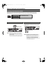
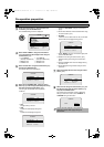
This equipment is indoor use and all the ethernet
wiring are limited to inside of the building.
1234
Maximum current: 0.5 A/125 VAC
Maximum voltage: 1 A /30 VDC
Power supply
External alarm device 1 - 4
L8HBT_WA(DSR-2116_2108)(GB).book 4 ページ 2009年5月27日 水曜日 午後4時50分